Hi! I'll be doing some environmental monitoring of formaldehyde (HCHO) next month as part of the SmART-Form project that is developing a low-cost formaldehyde detection system. In a couple of the homes we're going to be analyzing HCHO levels in real time to see how those real time levels compare to the system we are developing, which takes an average over three days. To do this we are using an Interscan portable HCHO meter. Here's the manual.
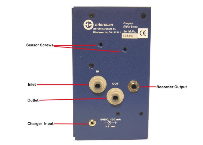
The meter has an output of the following specification: : ¼" phone jack for Analog recorder output connection. Typically 0-100mV. Tip --positive, Ring -- ground.
What public lab stocked data-logger would work best with this application?
Kind thanks for your help!

Any Arduino-based data logger should be able to read the signal from that sensor and save the reading at regular intervals. The main obstacle is that Arduinos do not have very good resolution for reading the low voltage signal from that sensor. Also, you must know how to interpret the results--although there is an analog output on the sensor, the manual does not say what the output signals mean or how to convert them to the proper units (e.g., ppb).
The sensor's analog output provides a signal that varies from 0 to 100 millivolts (mV). You will have to figure out how those voltages relate to the units of interest. The relationship could be linear or not. You could figure that out by noting what the sensor LCD says and what the Arduino says when different concentrations are sampled.
Arduinos typically have analog to digital conversion built in, so any analog pin (e.g., A1, A2, A3, ...) can read the voltage of the sensor output and convert it to a number. However, Arduino analog pins typically provide 10 bits of resolution and measure voltage between 0 and 3.3 volts (Pro Mini) or 0 and 5 volts (Nano). So if there are 1024 (210) increments between 0 volts and 3.3 volts, then the entire range of resolution from the sensor (0-100mV) will be expressed as 35 of the 1024 increments, and each increment will represent about 3% of the range of the sensor. There will be at most 30 different levels of gas concentration readings possible. That might be adequate, but it will be rather poor precision..
It is possible to amplify the signal or use a separate, low-voltage, analog to digital converter. I don't have experience with that, but many people do because that's what electrical engineers were created for. Here is a forum post from somebody doing the same thing. You won't like it.
You can also buy a module which will do what you need. I think something like this Adafruit 16bit ADC might do it, but I'm not sure.
Chris
Is this a question? Click here to post it to the Questions page.
@nshapiro - I think this is a provisional "yes" -- thanks @cfastie! Which is to say, a good follow-up question for the company is "how much resolution does your logger offer" so we have a sense of how an Arduino's ~35 possible values from highest to lowest compares to what they offer.
@cfastie @zengirl2 - does that sound right?
Is this a question? Click here to post it to the Questions page.
Thank you, Chris! This is extremely helpful, although a bit disappointing that none of the DIY data loggers would work without serious fiddling or losing precision. This little aspect is just one small part of an already logistically elaborate project so I think I'll have to look to other more expensive tools as I don't think I can really dive into the forums and figure this out on my own.
I'll try to sus out the relationship between the mV and ppb. The manufacturer was not especially helpful on the phone about this.
Is this sort of an anomaly or is it that diy data loggers work with diy digital-native sensors but not professional sensors as a general pattern?
Thanks again! I could really have seen me just assume any aurduino datalogger would work to plug and play only to find out it didn't.
Is this a question? Click here to post it to the Questions page.
Sorry, Nick I think it may still be an open question whether the manufacturer provides greater precision than this. Do you know?
And I think the part Chris mentions may also be relatively easy to plug in for greater precision. We'd be happy to help with that.
Is this a question? Click here to post it to the Questions page.
As to your other question about professional sensors -- I think there's nothing super special about the sensor you have, and almost any system (arduino/diy or otherwise) would have a pretty easy time reading from it. I think it's a little lower voltage than is usual, and it'd be cool if Arduino's supported that out of the box -- but there's nothing intrinsically incompatible.
In general, the professional sensors of this sort are probably charging quite a bit more than DIY not because the parts are especially amazing or special (talking about their datalogger here) but because they do such low quantities, and scientists are used to paying this much. Many lab instruments have actually been dramatically improved by attaching Arduinos to them instead of the built-in interface, since many companies don't have as much expertise or resources to build out a custom interface for each device. But there are exceptions where extremely high precision analog/digital converters are useful; still, I'd bet you could achieve similar precision for a fraction of the price with an open source system -- but it's not my area of expertise!
Ah okie thanks! this is all waaaaay over my head. thanks for the clarification re:professional sensor outputs. I think the precision is higher than that and I don't want to take any unnecessary risks. I asked the PI of the project if she has any data loggers we can use. it would be great if PL offered the 16 bit ADC option. I emailed the company this thread and will see what they say about precision.
Thanks, Nick - yeah, i think the ADC stuff is more complex than it should be!
Maybe we can recruit some help to get a basic Arduino sketch for this, using the Adafruit documentation:
https://learn.adafruit.com/adafruit-4-channel-adc-breakouts/assembly-and-wiring
https://learn.adafruit.com/adafruit-4-channel-adc-breakouts/arduino-code
I think it is par for the course that a random proprietary sensor will not work gracefully with an Arduino. In this case, it might be that a standard additional component (an ADC) is all that is needed to solve the electronic incompatibility issue. If that is true, then we are way ahead of the game.
In addition to the electronic incompatibility issue, we must know how the signal from the proprietary sensor should be converted to meaningful units. If the manufacturer will not tell us, we should not blame Arduino for the extra work required. It is not so hard to create a calibration curve and then tell the Arduino how to convert mV into useful units.
There are many people who could confirm that the Adafruit ADC will solve the electronic issue. You might have to dive into another forum to get that answer. In the meantime, I just ordered a couple ADCs on eBay. The $15 (plus shipping) ADC at Adafruit has been cloned and costs $2.42 (including shipping) from eBay sellers. It will probably work just like the Adafruit version using the Adafruit libraries and the Adafruit code. I'm not sure I have an appropriate sensor to test it with, but my impression is that an ADC is a standard component that will come in handy some day, and for $2.42, there is no reason to miss the opportunity to open the mailbox later this month and find a present from Shenzhen.
The top ADC is from Adafruit, the lower one is the $2.42 clone.
(I think the image in this comment displayed at one time but does not seem to do so now)
Unfortunately this is out of my league. You might try posting on Adafruit's forum asking about signal, but they won't be able to speak for the sensor you are using. I think Shannon Hicks would be the perfect person to ask since she has done a lot of testing with data-loggers too.
Thanks so much, Chris! So it does look like the relationship is linear between output and ppb. here is what a friend writes who has used this tool before: "0 mV equals 0 ppb (actually background of 5 -10 ppb).
100 mV equals full scale (which I think is 1000 ppb for the 1000b). Check with Interscan to verify the range of the unit.
Response is linear from 0 - 1000 ppb. However, response increases with ambient temperature. If you can control temperature, you will get more reliable data." I do have a rh and temp datalogger so its really just a matter of the ADC board now.
I'd like to try to get input from some of the many people at http://publiclab.org/contributors/datalogger who have almost certainly interfaced their Arduinos with a sensor with these requirements.
I think we could loop many of those people in here, OR we could post a follow-up more specifically asking "how do I connect and program this ADC" -- i'll send you the list of usernames we can
@mentionin a sec.8-Bit resolution is fine i'd think, you just need to amplify the signal. Any first year electrical engineering student worth her salt can design this circuit for you. I wish I had an electronics forum to send you to, but it's not my bag and I don't know a site.
Reading on it looks like the ADA Fruit might get you there. You just need to do some controlled testing to see that it is really linear output for ppbs of the gas you are monitoring and to see where in the line/curve temperature effects it and whether that is a linear step change in output or a more complete function to control for.
Maybe try https://electronics.stackexchange.com/ ? Stack Exchange sites are dependent on traffic for views to get good answers and this one looks a bit small, but worth a shot. It really is very basic to amplify a DC signal from low voltage range [0, 0.1] V range to [0,5] V range.
Is this a question? Click here to post it to the Questions page.
Reply to this comment...
Log in to comment
There is a very simple way to read the HCHO sensor with a resolution of about 10 ppb, assuming the range of the sensor is 0 to 1000ppb. (Out of the box an Arduino should read the HCHO sensor with a resolution of about 30 ppb.)
All standard Arduinos have a pin called "aref" (analog reference). By default the analog reference for reading analog signals is the voltage of the arduino board (around either 3.3V or 5V). But the actual voltage in the logic circuits of an Arduino can vary and is often slightly less than 3.3V or 5V. So for the precision reading of analog signals, you can supply a known voltage to the aref pin and the Arduino will use that voltage as the reference. Unfortunately, the lowest voltage you can supply to aref is 1.1V (1100 mV). With 1100mV as the reference, the maximum output of 100mV of the HCHO sensor would be 10% of the 10 bit range of the Arduino ADC. With 10 bit resolution (1024 increments) between 0 and 1100mV, there are 102 increments between 0 and 100mV. If 100mV represents 1000ppb, then each resolvable increment of mV equals about 10ppb.
The even better news is that you don't actually have to supply an external voltage to the aref pin. You can just tell the Arduino to use 1.1V as the analog reference. Include in the setup section the line
analogReference(INTERNAL);.
and the board will use 1.1V as aref. So if 10ppb is sufficient resolution, the HCHO sensor might work fine out of the box with this one line added.
Chris
this is actually an excellent solution to this problem without adding additional parts/complexity. The 1.1v internal reference is much more stable than using the 3.3/5v for ADC readings as well. Still not quite as stable as using an external device with a temperature corrected/calibrated reference voltage, but better. Might be worth looking at the specs of that and how much the temperature variance of the reference voltage would effect the readings at the resolution we're looking for. ....but it also might not matter in this application.
Reply to this comment...
Log in to comment
I'll just chime in here for a second as someone who has worked a lot with arduino dataloggers and ADC's, etc.
I agree with @cfastie on all points. Putting a 300mV signal into an Arduino analog pin will not be a good solution if you're looking for precision. However, many of the hobby electronics houses like adafruit or sparkfun sell ADC breakout boards. A quick search brought up this device which would likely work well. It also has what's known as a Programmable Gain Amplifier, which could amplify a low voltage input signal to take advantage of the full range of the ADC device for small signal levels like this sensor has. Building your own amplifier might be an easy task, but it would likely be more trouble that it's worth and add in more unknowns in regard to performance and temperature. AND with an off the shelf ADC like this one, you'll get performance/temperature graphs in the datasheet. I'd be happy to help dig through some datasheets to find this information, it's almost my favorite thing to do!
Also I have code kicking around for converting ADC values back into voltages, and would be happy to help work on the conversions from voltage into actual units.
Putting a temperature sensor inside of this device as close to the actual sensor as possible would be a really good idea, even if you're not doing temperature calibration correction right now, having the temperature data would make it possible to do later after you either get, or make temperature calibration curves.
SUMMARY: Use and External ADC for low voltages; Temperature calibration is important; I'd like to help!
AND actually a quick amendment to this regarding dataloggers: The Mini-Pearl would be a great build for the actually data storage half. The external ADC could just fit in in the place of the "I2C sensor" in the diagram at the top of the page. I haven't seen an off-the-shelf arduino based datalogger that works better than just wiring together breakout boards like this.
OK awesome @kinasmith and @cfastie ! What would be helpful for me to do as a facilitator to help Nick get all the way there? Here's some ideas: 1) i can set up a call for later today or tomorrow; 2) I can buy some parts and ship them to you quickly; 3)? Please let me know and i'll do it
Is this a question? Click here to post it to the Questions page.
Please give me a call at +1 336-269-1539
Kina, Thanks for the great information. Liz, It might help to know more about this project. What is the time frame for deployment? What has been tried so far? How many HCHO sensors are there? What data logger are you planning to use? What resolution are you hoping for? What is the minimum resolution you need? How much will the temperature vary where the logger is deployed? Will the sensor and logger be battery powered? How long must the device last on batteries?
Testing the sensor does not require a data logger, it just requires an Arduino (IOW, no SD card or RTC is needed). Hooking the sensor to an Arduino and watching the serial monitor will tell you a lot. Trying some different code for aref and converting mV to ppb is quick and easy. Has anyone done any of this?
Is this a question? Click here to post it to the Questions page.
Hi @cfastie -- thank you so much for asking these questions. Here's what i know --
Nick has to go to Georgia with a working solution in 2 weeks.
This solution is a secondary, real-time test serving as a comparison with the new badge that's part of the SmartForm workflow https://publiclab.org/wiki/smart-form.
The first step might be to arrange for the co-location of the HCHO sensor, an Arduino, and somebody casually familiar with Arduino. Has the proper "phone" jack been procured?
Is this a question? Click here to post it to the Questions page.
Perhaps @Zengirl2 can go over the Nick's house and bring an Arduino? (They are both in Philly) and for good measure we can open up a video link with @cfastie and @kinasmith
Is this a question? Click here to post it to the Questions page.
@liz I can meet with @nshapiro with some Arduinos, but I think my question is where do you attach alligator clips or wires for testing this beast?
Is this a question? Click here to post it to the Questions page.
New answer below where I could attach a file.
so, how long will the sensor need to collect data for? If there is reliable power, and it's inside of a house, and it isn't running for weeks on end, couldn't a possible solution be to just pipe a serial stream into a text file? If there is a laptop available, that might be a faster easier solution than trying to rig up an SD card and Real Time Clock, etc for remote datalogging. I think most of the commonly used serial terminal softwares have that as a feature (I know CoolTerm can do it).
Is this a question? Click here to post it to the Questions page.
^^ interesting! A whole new angle on this problem. I think I would actually do this first to see the results coming out of the sensor, whether or not i proceed to setting up a datalogger. I went to http://freeware.the-meiers.org/, scrolled down, and downloaded the CoolTerm version for Mac. Can the sensor be connected to the laptop via the same kind of audio cable? Will there be anything to type on the command line?
Is this a question? Click here to post it to the Questions page.
Here's what the interface looks like:
Can someone (@kinasmith ?) do a quick screen recording with CoolTerm open while talking about what menus and settings are needed to actually make a connection through a serial port? Also, what is a serial port? When I open CoolTerm, the window says "bluetooth-incoming-port 9600 8 n 1" . On my computer, I have a USB port, and HDMI port, an audio jack port, and that proprietary thunderbolt mac port. What cable can i use to what port? thank you
Is this a question? Click here to post it to the Questions page.
sorry, I wasn't very clear in that previous message. I'll try to clarify. You'll need an Arduino in the middle between the sensor and the computer. That's where the serial port comes from. A little bit of code on the arduino (modified from what cfastie posted) will basically convert from an analog input into a digital value, then print that out to the serial port. (https://gist.github.com/kinasmith/fd46b7c17b332520d0fb56f863e3ed15)
Quick note about the code. It will read in the voltage from the sensor on Analog Pin 3. Convert from the digital code (number between 0 and 1023) back into a voltage (between 0 and 1.01 volts), then send those out the serial port along with the milliseconds since the sketch started, and the adcRaw value. Each value is separated by a comma, so that it will be a CSV file when it's done being captured and can be imported directly into excel. You should be able to get accurate time stamps if you take good notes about when you start sketches, and what files are named, etc.
Regarding Coolterm: Once you have an Arduino plugged in (as long as you have the IDE installed and working etc, it should show up on that list of serial ports). I can't seem to get CoolTerm working right now on my computer, but here is an excellent looking tutorial for exactly what you're trying to do: http://www.reuk.co.uk/wordpress/saving-arduino-collected-data-to-text-file-on-windows/
Let me know how that goes. I'll have time tomorrow after 5pm (mountain time) to chat if you're available.
Hi @kinasmith this is extremely helpful! I have some additional information to report: the HCHO meter has already been sent to the research site in Georgia, whereas Nick and Leslie are in Philly. Do you have a phone number we could call and kind of talk through the feasibility of setting this up in advance if we don't have the actual sensor to work with? °_0
Is this a question? Click here to post it to the Questions page.
Email me liz@publiclab.org, if u can
I tried CoolTerm and never got it to work. I tried for only a half hour, so my failure is not so surprising. If you have a working data logger (e.g., Mini Pearl, Nano Logger, or Riffle), CoolTerm does not necessarily provide any ease of use benefits. It's easy to set you up with a sketch which will log data onto the microSD card of an Arduino data logger. You already have a sketch which will test the operation of the sensor.
So you need a data logger and the cable to plug into the sensor (which you have to build). You also want an AC/DC converter (phone charger) and cable (mini USB or micro USB [Riffle]) to power the data logger from mains power. A Mini Pearl Logger needs an FTDI (UART) adapter.
You will also need a few hours to tinker with the sensor and logger to get everything to work. Systems like this based on Arduino generally don't work the first time you turn them on.
Wow thanks @cfastie!!!!!! This is very useful info. Did you notice about that I mentioned @nshapiro and @zengirl2 don't have the actual HCHO sensor with them in Philly as it's been sent ahead to their field work site. Any advice?
Is this a question? Click here to post it to the Questions page.
Hello again. I just did two quick screen captures explaining how to do this with CoolTerm, using code from this GIST. The First one is here: https://goo.gl/t3fAwP The Second one is here: https://goo.gl/eMyzgX
Let me know if there are permissions issues with the videos. They're hosted on Dropbox right now. Also let me know if none of this make sense and I'll try to do better.
Kina, thanks for the videos. Very helpful. I might try CoolTerm again, since I was using a sketch that did not format the serial output in an appropriate way.
Liz, my last comment was directed at the person (Nick?) who will end up in the same room with the HCHO sensor and an Arduino. That person will probably have a time crunch and will want to have all the hardware and software ready to go (Arduino/logger, power source, cable for sensor, sketches). Other than gathering the hardware and software, there might not be too much else to do to prepare for that crunch, although getting comfortable with the Arduino could be important.
An important next step might be deciding whether to use a laptop or a data logger to save the data from the sensor. If you don't have a laptop to dedicate to the effort, the decision could be easy. If leaving a laptop running for the data collection period is possible, then it will be good to replicate Kina's video exercise. If you can't make that work, try a similar exercise with a data logger. What arduino would you use if a laptop was dedicated to the project? What data logger would you use if no laptop was involved?
Is this a question? Click here to post it to the Questions page.
Reply to this comment...
Log in to comment
A 1/4" stereo/phone plug connects to the HCHO sensor and two wires from that cable connect to the Arduino (tip of plug to A3, ring to GND). Below (he said hopefully) is a sketch for an Arduino which is completely untested and written by someone who has never tried reading a sensor like that.
HCHOtest1.0.txt
We're still struggling with a comment formatting bug -- apologies -- over in https://github.com/publiclab/plots2/pull/2605 -- here it is for the time being:
https://publiclab.org/system/images/photos/000/024/527/original/HCHOtest1.0.txt
https://gist.github.com/jywarren/599b76ef9cdecdce764a7348f728ae31
@cfastie @warren ah, ok that makes sense now.
wow awesome! @cfastie sorry to ask more but can you draw a picture on paper of what you expect these cables to look like? "A 1/4" stereo/phone plug connects to the HCHO sensor and two wires from that cable connect to the Arduino (tip of plug to A3, ring to GND)." -- specifically the "two wires from that cable connect to..." -- that's the part i can't picture -- what cable is "that cable"?. Also i'm communicating with Nick directly in case he hasn't been on the website today to help transfer all this
Is this a question? Click here to post it to the Questions page.
OK - links and uploads now working again on the site!
Thanks to all the software contributors who helped fix that -- @siaw23 @sagarpreet
Liz, I don't know the specs of the 1/4" phone plug, but it needs only two contacts, the tip and one ring along the shaft. I'm not sure which types of plugs will work (some have more than one ring). That plug terminates a cable with at least two wires in it. The wires from the tip of the plug and from one ring must be exposed and connected to pins on the Arduino.
I've read through the datasheet/manual for this sensor. Their use of audio connectors for signal and power connections is pretty questionable, but that is neither here nor there. The '1/4" phone jack" is a 1/4inch audio connector like this , it's the same used in instrument cables or microphone/amplifier audio connections. It's the "Mono" connector, which have a 'tip', the very end of the connector, and the 'sleeve', separated by a little band of plastic. Any old music/instrument cable could be hacked apart to use for this sensor. You'd just need to cut it, and strip the insulation to get to the two conductors, then do some creative soldering to be able to plug it into an Arduino.
Is this a question? Click here to post it to the Questions page.
ok thanks @cfastie and @kinasmith, i think i get it now!
Reply to this comment...
Log in to comment