Coquí: A Simple Water Conductivity Sensor
This is a beginner's guide to assembling the Coquí
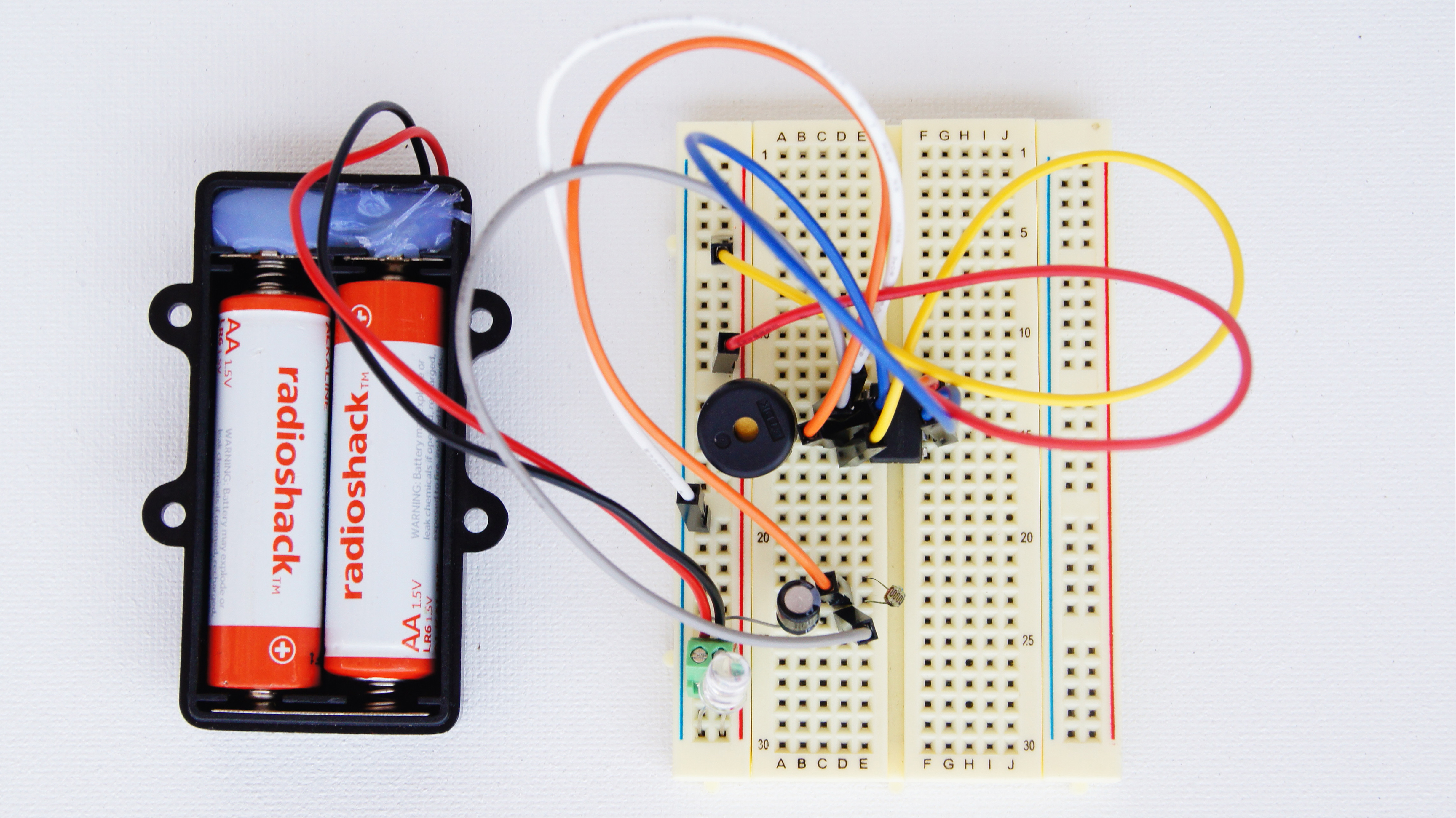
The Coquí is a simple water conductivity sensor designed by @donblair that is designed for use in an educational context. The coquí is a simple circuit assembled on a breadboard that has a speaker that outputs high frequency sound when the water conductivity is higher and lower frequency sounds when the conductivity is lower.
Want to measure something else? With simple modifications a Coquí can measure temperature, ambient light and LED light. Check out Don's original post to learn how.
Who is this for?
Buillding a coquí is a great way to introduce principles of water monitoring, DIY hardware, and sensors to new audiences. @kanarinka and John Keefe use coquís to teach workshops in sensor journalism. The coquí is featured in the Educator's Guide to Sensor Journalism pamphlet by @kanarinka (forthcoming in Fall 2016).
Duration
Assembly will take around 30-45 minutes for a novice, including troubleshooting and debugging.
Ingredients

Resistor (R) tunes the frequency of the 555 output (which we'll be hearing via a speaker)
For low conductivity solutions, 0.1 uF in a capacitor (C) is a good range to use. For higher conductivity solutions (like salt water), 1.0 uF, or even 10.0 uF, might be better values to use, in order to keep the output frequency in the audible range.
The frequency of the output is a function both of the resistance, 'R' (which can be either a resistor, or some water between two electrodes, or a photo-resistor, or a thermistor, or a potentiometer ... anything that will provide an electrical connection, with some resistance), and a capacitor, 'C'.
The frequency of output is given by: 0.7/(R*C).
Step-by-step guide to assembling the Coquí
Attach the 555 chip on the breadboard.

Connect pin #4 to VCC.

Connect pin #8 to VCC.

Connect pin #2 to pin #6.

Connect the speaker to pin #3 and GND.

Connect pin #3 to some row.

Connect pin #2 to a row right below previous.

Add a capacitor from previous pin to GND.

Connect pin #1 to GND.

Using a photocell as a sensor: add the photocell between the previous two wires.

Connect the battery (positive / red to VCC, negative / black to GND).

Place an LED between VCC and GND to make sure there's power, when debugging (Optional).

DONE!
Learn more about the Coquí in context
- Don Blair's original post, including more technical information and modifications
- A round-up of John Keefe's use of the Coquí in West Virginia with Journalism students
- Photos of building the Coquí with @liz in Hong Kong
- Journalism student @mattmullen reflects on the potentials and pitfalls of sensor journalism