The Simple Air Sensor is built using the same Plantower particulate sensor used in the Purple Air, but only one as compared to #PurpleAir's two; does not have a BME280 temperature, humidity and pressure sensor as the #PurpleAir does; and does not log or upload data, but it shows the reading from its PM2.5 sensor as a colored light, where warmer colors indicate higher readings NOT an Air Quality Index (AQI). It's not intended for data collection, but to help you get a better understanding of how sensors work, and for use alongside fancier sensors. You can buy one in the Public Lab store, or find the parts (listed below) yourself.
(note: if you have the Arduino program and the right drivers, it will output data over serial, but it can be hard to set up)
Once built, try keeping it around your house or yard and seeing how it reacts when sources of particulate/dust pollution occur. I keep mine next to the stove while I cook, which is interesting to watch.
Parts list
- an Arduino Nano
- an RGB LED (common anode)
- a Plantower 5003 or 7003 sensor
- a mini breadboard
- a mini-USB cable
Note that in the below picture, the three wires connected to a square white plug are shown incorrectly; the left-most wire should be green. We'll correct this soon, but it's been corrected in the rest of the images in this guide.

Step 1: put the Arduino onto the breadboard
Plug it in - it'll take some strength, but you can push the middle quite hard. If it's sharp, try putting some cardboard over it so you don't hurt your fingers!
The exact position isn't super important since the pins are labeled.

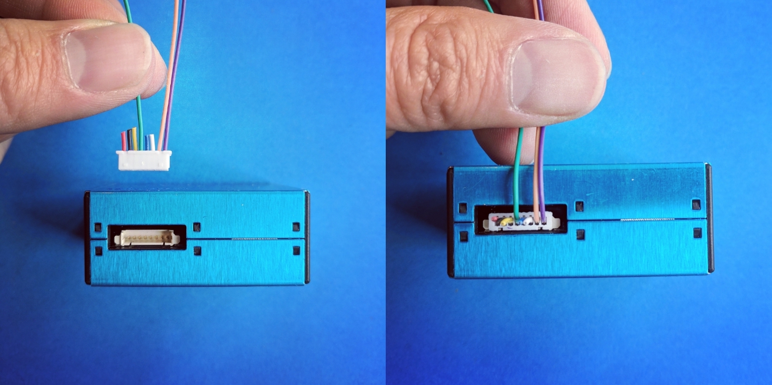
Step 2: plug in connector cable
Connect the ribbon cable to the sensor (the blue box) as shown below, with the free wires towards the middle of the box. Use your fingernails or a small screwdriver to insert the cable solidly.
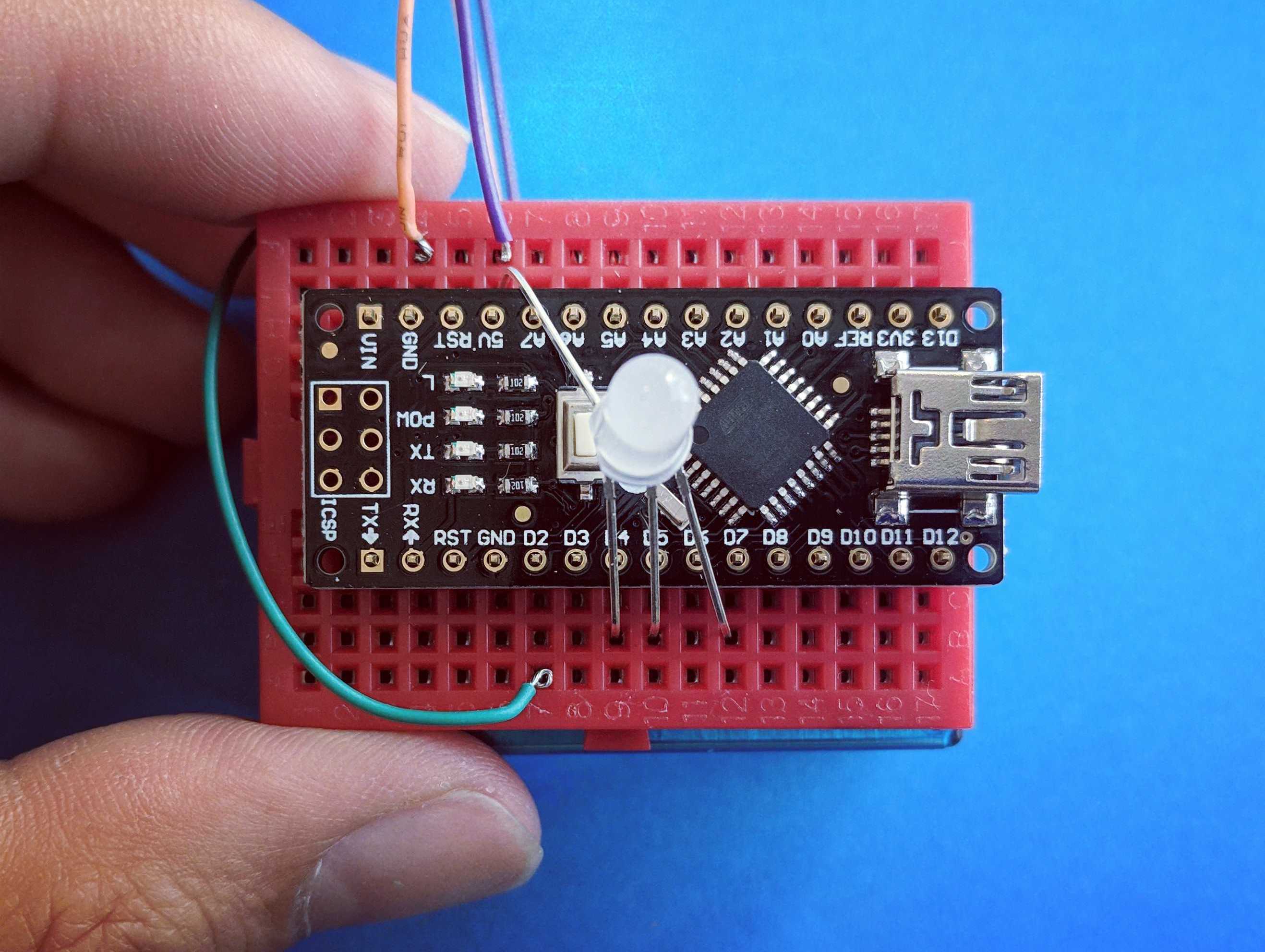
Step 3: attach breadboard and insert wires
Peel the sticker paper off the back of the breadboard and attach it in the orientation shown (you could also do this differently if you have a different enclosure, but this is nice and simple). Then insert the wires as shown into the 5V (five volt, shown in purple), GND (ground, shown in pink), and D2 (the digital pin for transferring the data, shown in blue).
On the sensor, the order is, from the right to left in the above image: 5V**, GND, D2**, and they are, again from right to left, the first, second, and fifthwires.
The breadboard holes are connected in vertical rows (though not across the center trough), so you can insert the wires in the holes just above or below the marked pins on the Arduino, as shown below.

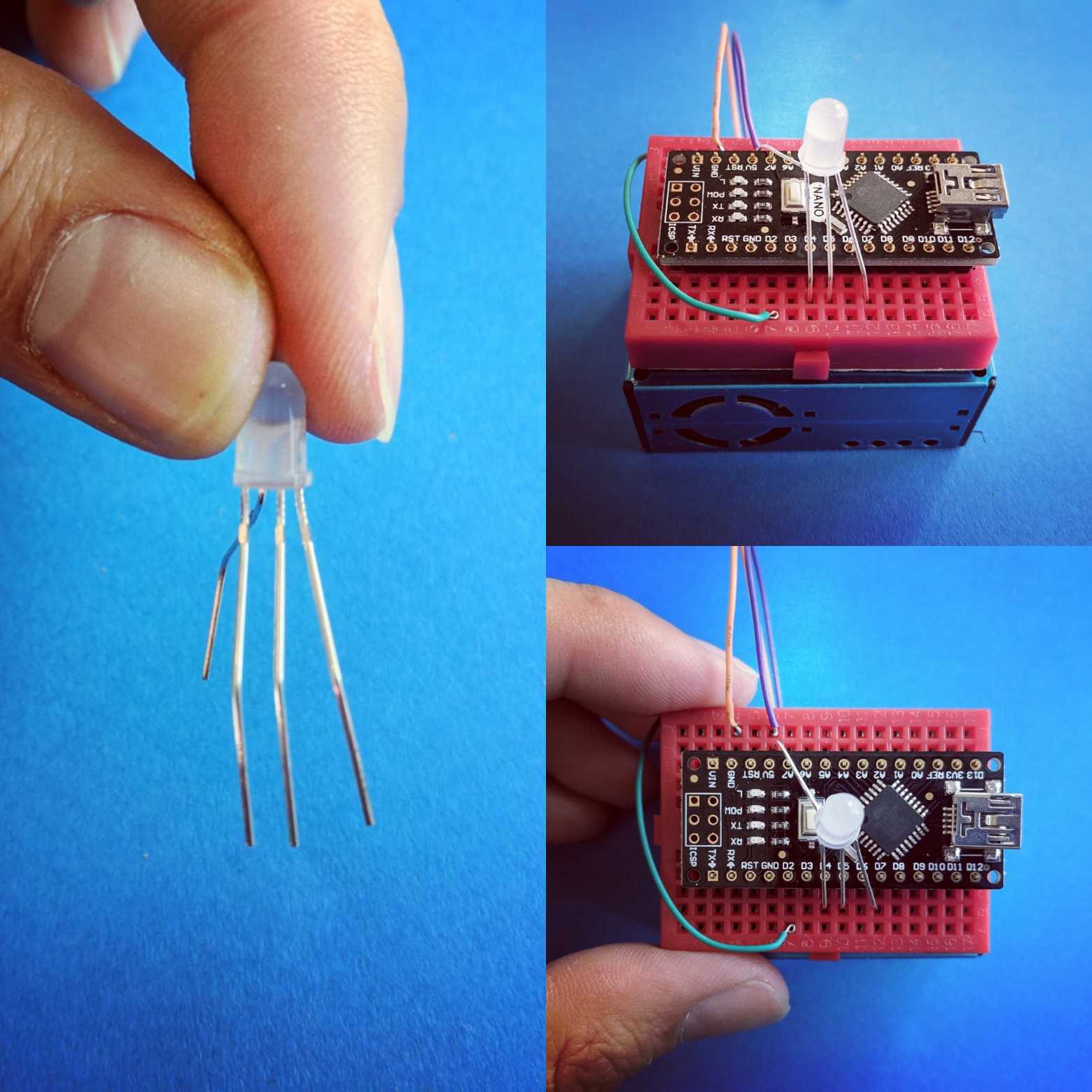
Step 4: attach the LED light
This is maybe the hardest step: the pins of the LED light can be bent in such a way as to let you plug it in directly "straddling" the Arduino board; this simplifies the layout and reduces wires, but it's not super simple. We'll post soon on using an "extension cable" to do this without needing to do this straddling, but for now:
Bend the longest pin (that'll go to the positive 5V source) away from the others, as shown below.
Now, space out the 3 remaining legs so they can be inserted into D4, D5, and D7. I found it simplest to do this first, then to bend the 5V leg diagonally so it could be inserted into the hole next to the 5V pin of the Arduino, as shown below.
(Note: if you bought your own LED, it should be "common anode" so that the long pin goes to power, not ground.)
Notice that as shown below, I've bent the 2nd leg (counting left to right) back, and the other three towards me.
Step 5: plug it in
If you've bought this kit from Public Lab, it'll be already programmed with this program: https://create.arduino.cc/editor/jywarren/ce8d09fc-3f5f-4d6b-bb0f-4aea24838fbe/preview (here's a simpler Gist link too) However, if you've bought your own or got it elsewhere, you'll need to program it first, using this program.
If it's already programmed, you can just plug it in using your USB cable, to basically any USB power source, like a battery or laptop.

Finish up
We'll post on using this sensor soon, but it may be very worthwhile to place it inside a semi-open container like a cut open bottle, a tube, or a yogurt container, so that the wires are protected from coming undone.
You can also put strong tape (or even hot glue) over the wires to protect them, although be aware that the more you affix them, the less you'll be able to make changes later. Do it only when you're sure it's working properly!
I'm sure we've missed some steps here so please offer some feedback and help us improve the guide! Thanks!
8 Comments
Hi @sadieprego - would you like us to send you one of these?
Is this a question? Click here to post it to the Questions page.
Definitely!
Reply to this comment...
Log in to comment
@wmacfarl also did you do your workshop with these yet?
Is this a question? Click here to post it to the Questions page.
Reply to this comment...
Log in to comment
Nice kit!
Main constructive feedback I would offer is that the cable that came ahead of the "Make" livestream event would have been hard to breadboard. I separated the wires (easy) and tinned them with some solder. That soldering step might be a barrier for some but made hookup much easier.
For a quick fun demo we've been lighting matches and candles and then blowing them out. It's surprising how long the area stays red/orange afterwards!
Reply to this comment...
Log in to comment
We are having some issues with our sensor. It does turn green around clean air, but it only turns blue around unclean air (smoke, etc.), not red or yellow. We don't know why this is happening, or how to fix it. Any tips?
Is this a question? Click here to post it to the Questions page.
Reply to this comment...
Log in to comment
Can you use an ESP32 board instead of an Arduino nano?
Is this a question? Click here to post it to the Questions page.
Hi @lilymccraith, nice to see you here!
Great question about alternative parts for the Simple Air Sensor. I'm not sure of the answer myself, but would you be interested in posting this as a separate question post? Hopefully we can get more eyes and input on it! If you follow the "Click here..." link under your comment, it should take you right to a question post form.
Is this a question? Click here to post it to the Questions page.
The Plantower sensors require 4.5 to 5.5 volts. They work well with 5 volt Arduinos. They might not work properly with ESP8266 or ESP32 boards because they are 3.3 volt boards. The Plantower sensors might limp along with 3.3 volts. It's always possible to use separate power supplies for the board and the sensor. But then the sensor might send a 5 volt data signal back to a 3.3 volt board. There is no harm in trying (unless toasting a $5 board is considered harm).
PurpleAir sensors use a Plantower sensor and an ESP 8266. So it can be done if you know how.
Chris
Reply to this comment...
Log in to comment
Login to comment.