What I want to do
- Continue where Part 1 left off, exploring Riffle and Arduino documentation
- Part 3 is an activity building the physical circuit.
- Clean up all parts in the series with final editing.
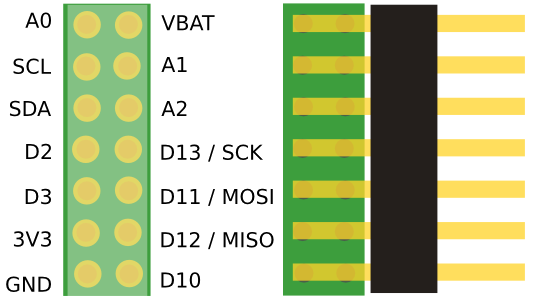
A primer on pins
Looking at the example sketches in the riffle repositories, I noticed the functions PinMode() and DigitalWrite() prominently used. Some quick google searches led to learning about the differences and capabilities of the digital pins, and analog pins. I'm just after a working knowledge to build off of other sketches, so I skimmed these sections on the Arduino tutorial:
- Digital Pins: How the pins work and what it means for them to be configured as inputs or outputs.
- Analog Input Pins: Details about the analog-to-digital conversion and other uses of the pins.
- PWM: How the analogWrite() function simulates an analog output using pulse-width modulation.
I also found the help pages for those two functions:
https://www.arduino.cc/en/Reference/PinMode https://www.arduino.cc/en/Reference/DigitalWrite
Some interesting ideas emerged. First, I learned a few ways that it's possible to break an arduino, and probably the riffle too -- by short circuiting connections from the pins to the ground -- making a circuit that doesn't have enough resistors/resistance, which allows too much current to go through. I read an entertaining article about more ways that electronics can break an arduino, and now feel sufficiently warned to treat all these electronics with careful planning.
Second, I'm not sure about the 3V3 and GND pins. Do they differ in hardware from the other digital pins, to be better at supplying voltage and ground to the circuit? Can they support higher current draw? What is the story with these pins?
Looking at @donblair 's example circuit and sketch, the thermsistor, which makes use of 3V3 and GND: https://github.com/OpenWaterProject/riffle_328-thermistor
Here's the schematic:

And the code snippets regarding the pins:
Initializing the digital pins:
const int led = 9; //Feedback LED
const int bat_v_pin = A3;
const int bat_v_enable = 4; //enable pin for bat. voltage read
const int rtc_int = 5; //rtc interrupt pin
const int sd_pwr_enable = 6; //enable pin for SD power
const int hdr_pwr_enable = 8; //enable pin for header power
. Enabling the Analog pin
// which analog pin to connect
#define THERMISTORPIN A0
. Putting the pins in the correct mode
// put the external sensors switch in the right mode
pinMode(hdr_pwr_enable, OUTPUT);
digitalWrite(hdr_pwr_enable, HIGH); //Turn off external sensors
. Powering the circuit (to take thermistor readings)
// turn on external sensors
digitalWrite(hdr_pwr_enable, LOW); //Turn power external header
. (re:formatting: I used dots between the code blocks to get the formatting to look right in markdown)
From what I can make of this, I'm guessing that not every numbered pin is exposed on the pin out. Pin #5 is the RTC interrupt pin, #6 powers the SD card, #9 controls the onboard LED. I think that #3 is a pin leading to the battery, and #4 is the VBAT pin on the pinout that reads what the battery voltage is -- but I'm in way over my head here. (I will update this text once I know what they mean for sure). The analog pin being used is named A0.
It looks like #8 might correspond to the 3V3 labeled pinout, if that's what header power refers to. And the pinMode() and digitalWrite() commands are being used to supply voltage to the sensor or not using the 3V3 pin.
Questions and next steps
It seems that now I have enough information to be dangerous with the riffle hardware.
- Are there any GLARING ERRORS in what I've pieced together? :)
- Is it possible for research notes to do code highlighting the way it looks in github?
- Can I modify an existing sketch and make a breadboard circuit that blinks an LED? Tune in next week for Part 3 to find out. Literally -- I'm going to be on a camping trip until Sept 27th!
Why I'm interested
Eventually I'd like to work on the conductivity circuits that others have been working on!
1 Comments
Turns out the code blocks still didn't format correctly -- I'll try again this time using the four space indent system rather than the ``` ``` system
Reply to this comment...
Log in to comment
Login to comment.