Last fall I started to look into methods to calibrate near-infrared cameras to measure reflectance. The intent of this work is to develop a simple and objective calibration work flow to facilitate the production of accurate NDVI images. The initial tests were conducted using materials I had laying around the house (e.g., pine boards, pink fiberglass, tar paper) and I used spectral reflectance curves from online spectral libraries to characterize the reflectance properties of those materials. The results were promising so I am picking up where I left off.
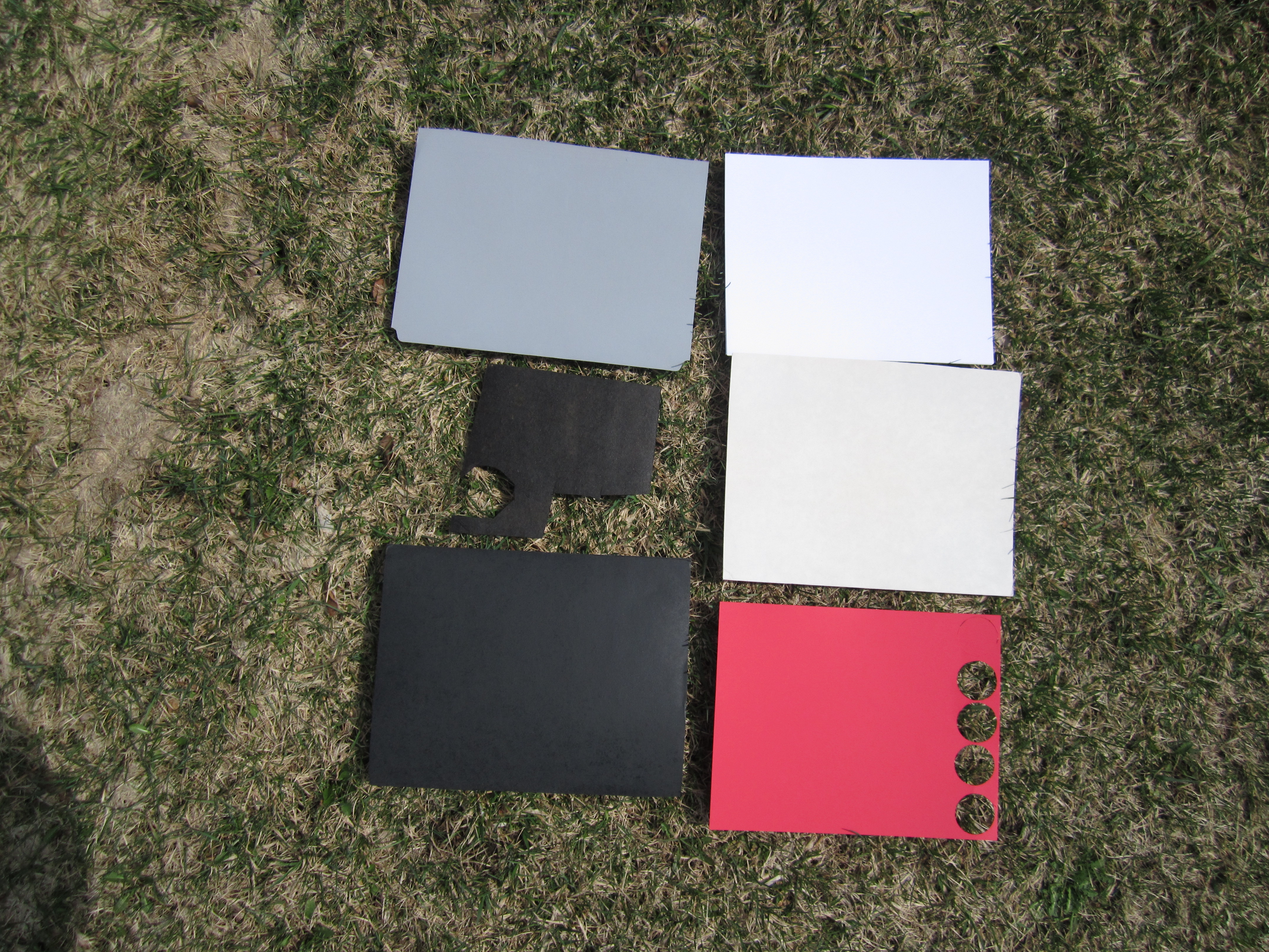
To improve upon the initial research I wanted to use reference materials that could be characterized using a spectrometer instead of relying on spectral libraries. I contacted Mary Martin from the University of New Hampshire and she graciously agreed to scan some samples using a FOSS NIR6500 benchtop scanner. I sent her the following samples:
- Black spray paint
- White spray paint
- Gray spray paint
- Tar paper
- White printer paper
- Red card stock
The spectral curves of the scans are below. Two scans of each sample were acquired.

Spectral curves of the sample calibration targets
.
To test these new calibration targets I took a photo of them using a Canon 2200 camera with a Wratten 25A (red) filer. Next, I used Fiji to extract the average pixel values for rectangular regions of interest for each of the targets using the Analyze => Color Histogram function.

Extracting sample pixels from the calibration targets in a region of interest using Fiji
.
The average pixel values for each image band were entered into a table:
| Target | Red | Green | Blue |
|---|---|---|---|
| Black spray paint | 41.62 | 43.6 | 48.16 |
| White spray paint | 219.19 | 220.53 | 214.46 |
| Gray spray paint | 148.81 | 150.45 | 154.11 |
| Tar paper | 37.68 | 42.25 | 50.29 |
| White printer paper | 218.99 | 219.51 | 214.42 |
| Red card stock | 219.19 | 218.35 | 222.93 |
Mean pixels values in the red, green, and blue channels of the calibration target photo
.
For each target I plotted the average pixel values for the red band vs. the reference reflectance value recorded at 650 nm (red) and then plotted a linear regression line.

Regression of pixel value vs reflectance (as measured by a spectrometer)
.
I noticed the point representing the gray spray paint was a significant distance from the line. After some thought I realized this was the likely result of the gamma correction (http://en.wikipedia.org/wiki/Gamma_correction) that is applied when the image in converted to a JPEG inside the camera to make the camera sensor mimic the response of a human eye. The camera sensor records light intensity more or less linearly (e.g., if twice as many photons hits the sensor the pixel value will double) but our eyes are more sensitive to low-light conditions than they are to brighter lighting so a gamma correction is applied (unless you are recording in RAW in which case the sensor response is linear) to brighten darker pixels. To transform the image pixel values to their original linear response I inverted the gamma correction formula [linear response pixel value = jpeg pixel value ^ (1/gamma) where “^” is the power function]. I didn't know the value for gamma but after some testing I found that a value of 0.35 worked reasonably well. Here is the plot after applying the inverted gamma correction.

Regression of pixel value (after removing the gamma correction) vs reflectance (as measured by a spectrometer)
.
You can see the outlier point is closer to the regression line. I calibrated the red and blue (NIR) bands by applying the gain and offset (slope and intercept) values from the regression to produce reflectance images. The reflectance images were then used to calculate an NDVI image [(NIR – Red) / (NIR + Red)]. The NDVI values in the image seem to be within the range of values I expect. In the image below the grass has NDVI values between 0.6 and 0.7.


Color NDVI image
.

Grayscale NDVI image (black is low NDVI and white is high NDVI
.
I should note that the targets I selected are not ideal but I was trying to use material that would be easy for people to purchase. If there is interest in this sort of calibration it might make sense to investigate manufacturing a stable and portable calibration card.
The next step is to test this work flow with different cameras. If the results continue to look promising I'll work on ways to simplify the process. The processing is still somewhat cumbersome but the intent is to develop an easy to use automated (or at least nearly so) method for calibrating photos so we can create NDVI images using objective methods. Ideally the process would involve taking a photo of a calibration target before a photo mission and then use software to read the photo of the calibration target and automatically extract pixel values and calculate the calibration coefficients which would be used to create NDVI images from the other photos.
48 Comments
Ned,
This approach looks really promising. I was writing a comment about how this fit in with our current way of making NDVI when I realized I didn't understand how it fit in. I couldn't answer these questions:
And I have a follow-up.
Chris
Is this a question? Click here to post it to the Questions page.
Reply to this comment...
Log in to comment
Chris - Here are some comments to your first round of questions:
How does this apply to dual camera systems, or does it apply only to single camera (Infragram) systems? (I think both)
This type of calibration should work for single unmodified (visible) and modified NIR cameras as well as dual NIR/visible cameras. The goal of calibration is to convert the pixel values in each band of a photo to a physical measurement - reflectance.
Is this approach objective as opposed to subjective? (I think yes) What makes our current approach subjective, and what makes this approach objective? (I couldn't articulate an answer)
Yes - this is objective instead of subjective. The current approach is to play with histogram stretches and white balance until we get an image that looks reasonable. That's fine but the results will depend on the person doing the processing. By calibrating the image bands to physical units we don't have to rely on our perception of what looks good.
In what ways will this make the NDVI results better than our current results? (precision, accuracy, believability, comparability, interpretability)
Assuming the calibrated images are reasonably accurate I think the primary benefit will be consistency between different cameras and missions. I should also make it easier for most people to create reasonable NDVI images since most folks don't seem to have much experience working with NDVI. I expect someone like you would be able to create output similar in quality to what you would get using a calibration routine. Another advantage for me is that I simply like working with data that can be associated with physical values.
Is this a question? Click here to post it to the Questions page.
Reply to this comment...
Log in to comment
Ned, thank you for your tremendous effort in this field. I have been following your work here and reviewing Geert Verhoeven's previous research very closely. I am a graduate researcher at Oregon State University and calibration of Canon cameras converted for NIR sensitivity is highly desirable for my research. I have several converted cameras: Canon G15 (590 nm filter), S100 (830 nm filter) and Sony NEX 5T (665 nm filter). I soon will be adding a NEX 5T with 590 nm and a S110 with 590 nm filters. I have unmodified duplicates of most of these cameras. I would like to offer my assistance toward your objective of producing a simplified calibration workflow and calibration cards. I may also have access to the spectroscopy lab on campus if necessary. If you are interested let me know.
Reply to this comment...
Log in to comment
Ned, From Mary’s scans, you knew the reflectance of your colored targets for every visible and near infrared wavelength. But it looks like you used only the data for 650 nm (red) to do the calibration. Would you get a different answer if you used other wavelengths? Could you use several at once?
Your targets included a red card, but the others were white, gray, or black. Would it be better to also have a blue and green target? Or is the spectral curve of each target more important that the perceived color? Chris
Is this a question? Click here to post it to the Questions page.
Reply to this comment...
Log in to comment
Hi jdburnett – It sounds like you have quite a nice collection of cameras. It would be great to run some calibration tests with different cameras and different targets. It would also be nice to be able to test the results of the calibration using a field spectrometer to see how well the calibrated images produce NDVI values of a landscape. A desktop spectrometer could also work if you can get vegetation samples prepared and scanned quickly enough. I've been using R scripts for all of my processing since it can calculate the regression coefficients and create the NDVI images. I'm happy to send you the scripts I'm using if that's helpful. If you want to talk about this we can set up a call.
Chris – I used 650 for the red just because that seemed to be a good number to start with. I want to test other wavelengths to see which give the best correlation. That can be automated with the scripts I'm using. I also want to simulate broad band reflectance using an average. Is that what you meant by “using several at once”? I'm not expecting that to make a significant difference but it should be tested.
I don't see an advantage of using different color targets unless perhaps we are calibrating an RGB camera. It seems like some colored material, like construction paper, has a similar NIR response regardless of the color. The best targets would have a relatively flat response across all wavelengths but those are a little costly. I have a feeling that a black and white target would work quite well. With fairly simple testing we should be able to find some answers to these questions.
On a related note, although I tried to remove the effect of the gamma correction in my first test I'm not certain that's necessary. If the same gamma correction is used for all bands then I think that effect (nonlinear sensor response) will disappear in the division of the NDVI formula. That also needs to be tested.
Is this a question? Click here to post it to the Questions page.
Reply to this comment...
Log in to comment
How close is this to what you are trying to do?
NDVI depends on the difference between two values:
Cameras make photographs by sensing this reflected light, but the sensed amounts of light that would reach each pixel are modified in order to make a photo that appears realistic to our eyes. So before the camera produces a jpeg photo, gamma correction has made dim areas of photos brighter, white balance corrections have systematically changed the relative brightness of the three colors recorded in each pixel, and other corrections are probably made to make the colors more realistic. So the difference between the amounts of light in the red and blue channels no longer relate simply to the amounts of red and blue light that were reflected from the scene and arrived at the camera sensor (in the Wratten 25A camera used here, the red channel records visible mostly red light, and the blue channel records near infrared light).
In order to adjust the jpeg so that the brightness values for each pixel more closely represent the actual amounts of reflected light in the scene, we have to know how those two things are related. For example, if there are two colored surfaces in the scene and we know (because a spectrometer measured it) that one reflects twice as much red light as the other, we can take a photo and then adjust the jpeg so that the value for red for the brighter surface is twice that of the other. With several different surfaces we are able to get a mathematical relationship (regression) between actual reflected light of any color and brightness recorded for that color in the jpeg. Then the red, green, and blue (NIR) values for every pixel in the jpeg are adjusted (new value = some function of old value). I think a single function (equation) could be used for all colors, but maybe separate equations could be used for each color.
Is this a question? Click here to post it to the Questions page.
Reply to this comment...
Log in to comment
Chris,
What you describe is part of what I'm trying to do. I want to take your description one step further so that the “new value” represents a physical measurement – reflectance. I expect that the basic function will be the same for each color but the coefficients will be different since, for example, white balance will effect each channel (color) differently.
Well said. A lot of what I'm trying to do is to better understand the processing going on in the camera. The gamma correction process seems to be well documented but I'm still not sure if white balance does more than multiplies pixel values in a particular channel values by a constant or if it's more complicated than that. The only other processing that I am aware of is a scaling between the gamma corrected RAW pixel values and the JPEG values and some lossy compression but maybe there is more going on.
Reply to this comment...
Log in to comment
What is the additional step to get a reflectance value? You are estimating the brightness of the reflected light arriving at the camera by using a regression of jpeg digital number (independent variable) against reflected brightness (dependent variable). Do you just call that estimate reflectance or is there an extra step?
Is this a question? Click here to post it to the Questions page.
Reply to this comment...
Log in to comment
I guess it's not actually an extra step. When I do the regression I'm comparing the JPEG pixel values that I adjusted with my inverse gamma (un)correction with the reflectance values I got form the spectrometer. The regression established the relationship between those two values and then I can then use the slope and intercept (gain and offset) coefficients from the linear regression to convert the image (after I applied the inverse gamma (un)correction) to reflectance.
Reply to this comment...
Log in to comment
Ned, I'm not sure how much this information would help you out here, but I just finished my research thesis, which looked at the NIR sensitivity of the red, green, and blue bayer mosaic channels of a Canon Rebel T3 that had its hot mirror replaced with glass. I did the study on 3 different targets, using RAW. Here are the takeaway points that might interest/inform your research:
The blue, green, and red channels on the sensor all have sensitivity to NIR; blue has the least, and red the most. Also, the reflectance of the target in the NIR impacts the correlation/covariance between the channel's normal wavelength (ie. blue) and what it picks up in the NIR. If the target has a high NIR reflectance, then the correlation between the NIR portion of the DN value and the Blue (or red, or green) portion is much greater >.85 r2. When the NIR reflectance of the target is moderate or low, the correlation is much less.
Basically, the difficulty with calibrating the images will arise when an image has many different objects/targets, at which point, for a calibration that is better than a coarse estimate, the spectral reflectance of every target would need to be known and calibrated with the corresponding 2 wavelengths in each pixel (in a single camera, dual bandpass solution). For a multi-camera solution, it is still important to consider that the NIR reflectance of the target affects how much the red/green/blue bayer mosaic filter allows through to the sensor.
Reply to this comment...
Log in to comment
Hi Roolark - Thanks for posting your comments and sharing your research. I don't know if you can post a link to your thesis but I'd be interested in reading it. Your observations match what one would expect from the sensor transmission curves that have been posted. I like that you highlight the correlation behavior when observing different objects with high NIR reflectance. The odd thing is that in my limited experience the effect is significantly less than I expect that if should be based on the sensor/filter transmission curves. It's quite possible it's an illusion and some day soon the adverse effects could become more obvious. We will always have issues related to the very broad bandwidth of the camera channels but I expect they will still provide useful data. I hope you continue to report on your research.
Reply to this comment...
Log in to comment
...the NIR reflectance of the target affects how much the red/green/blue bayer mosaic filter allows through to the sensor.Roolark, I would think that the Bayer filter always transmits the same proportion of wavelengths (it's just a filter), but that the sensor may respond differently when impacted with different proportions of NIR and visible light. Does the Bayer filter actually filter differently when there is more or less NIR impacting it?
Is this a question? Click here to post it to the Questions page.
Reply to this comment...
Log in to comment
Ned, I am getting access to a spectrometer soon. I'll be in touch once I do.
Reply to this comment...
Log in to comment
Roolark,
Would you be willing to post a link to your thesis or some more details regarding how you manipulated RAW data? I am interested to know if you used MATLABs functionality to extract RAW sensor data without applying a WB correction? There is no sense in us covering the same old ground. It may be that specific cameras have to be calibrated for a specific object.
Is this a question? Click here to post it to the Questions page.
Reply to this comment...
Log in to comment
Could i replicate this easily if i had purchased a photographers' white balance cards? would it look the same? I'm using the infragram.1.0 2-camera system with A495s and exposed film as a filter
Is this a question? Click here to post it to the Questions page.
Reply to this comment...
Log in to comment
Hi Scott, It might be possible to calibrate a camera using a single color like a white balance card but at the very least you would need to know the reflectance value of the card and you would need to characterize your camera. The second step is the tricky part and the process I'm developing requires a few colors to do the characterization. I am trying to work on this calibration issue but have been distracted with other tasks and there are some issues in the calibration process that I'm trying to better understand so progress is slow. Some of my results are puzzling so I'm trying to get a better handle on cause and effect. So the simple answer to your question is "no". For now, if you want to use a white balance card I'd use the methods Chris Fastie has outlined in previous posts. That (and histogram stretching) is more of a relative calibration but it can be used to make useful images.
Reply to this comment...
Log in to comment
Hi ned. Thank you for posting your work.
I was wondering, and I just want to check, for flying a small UAV with a single NIR camera, with the calibration method you propose: - The white balance has to be repeated every flight on the same target? - A photo of the same targets with known reflectance must be taken every flight, for computing the reflectnace vs. pixel value regression ?
If this is right, this adds some extra effort to the take-off procedure. Do you have any idea on how could this be reduced?
Thanks again for your posts :)
Is this a question? Click here to post it to the Questions page.
Reply to this comment...
Log in to comment
Hi manattta - Keep in mind that white balance and calibration are two different processes. White balance is used to adjust the in-camera processing with the goal of making a photo look "nice". In our case we're interested in creating a photo that makes a decent looking NDVI image without much additional processing. The goal of calibration on the other hand is to convert the pixel values recorded by the camera to a physical measurement. In our case we want to convert to reflectance.
With both white balance and calibration it is best if you can image a target under lighting conditions that are similar to the lighting conditions when you will be acquiring your aerial photos. If you add that step to your aerial survey protocols it's not much extra work. In addition to a pre-flight target shot its probably a good idea to take a post-flight target shot too.
If you don't want to use a target during each flight you can do the calibration once and then assume the lighting conditions (sun elevation, azimuth, atmospheric conditions) are similar for each flight. That might be good enough for your work. Another option is to adjust for different illumination factors when you post-process your images but that would require developing an appropriate model and recording solar intensity and angle during your flight missions. That would be an interesting project but would not be easy.
Reply to this comment...
Log in to comment
Hi ned! I would like to ask you how do you setup the camera? I have a canon power shot a490 with red filter, i try to a similar test but with bud results. How i should put the differents settings in the camera? Automatic? Program? Iso should be 100 ? Expouse brigghtnes? -2 or 0 +2 i 'll apreciate your opinion. I put a white paper and a black plastis maybe there are not the right materials.
regards. Agustin
Is this a question? Click here to post it to the Questions page.
Reply to this comment...
Log in to comment
Hi Ned me again, could be that the analisys that you did it was over the image without the red filter? because when i read the article i understand that you did the analisys over the picture using the camera with the red filter? that is confusing to me. could you please explaim me? Thanks
Agustin
Is this a question? Click here to post it to the Questions page.
Reply to this comment...
Log in to comment
Hi Agustin - I have a feeling the problem with with the calibration targets you are using. The targets I sued for this note were scanned by a laboratory spectrometer so I know what the reflectance properties were. What I did before I had these targets was look for material that had reflectance properties published in spectral libraries. Look at my first calibration research note for more information and link to some libraries: http://publiclab.org/notes/nedhorning/10-21-2013/calibrating-diy-nir-cameras-part-1
If you're doing calibration I suggest taking images in RAW format it possible. If that's not possible you need to remove the gamma correction (described above) that was applied before the image is saved as a JPEG. The camera settings should make much of a difference as long as they are the same setting used when you took an image of the calibration targets.
I did the correction on a photo that was acquired using a camera with a red filter.
I hope that helps.
Ned
Reply to this comment...
Log in to comment
Thanks Ned. I have a red filter (600nm) and the filter color is red and the pictures that i take with this filter are red why you have a similar filter and your pictures are blue? This point is confusing me.
Is this a question? Click here to post it to the Questions page.
Reply to this comment...
Log in to comment
The image for this note with the blue color was probably a JPEG image white balanced using red paper. The raw image will have much higher values in the red band so that image would appear reddish.
Reply to this comment...
Log in to comment
@nedhorning
Hello Ned,
I have calculated ndvi using following code in matlab, using single camera without white balancing:
red_orig = imread('IMG_RED.TIF'); nir_orig = imread('IMG_NIR.TIF'); red = im2double(red); nir = im2double(nir); ndvi = (nir - red)./(nir + red);
Suppose I'm having reflectance Kr and Kn of RED and NIR band respectively in percentage (80% both), and also having average pixel value for RED and NIR, Vr and Vn respectively.
Now how can I incorporate these for calculating the true NDVI in the equation?
Please help me with this. Thanks a lot.
Is this a question? Click here to post it to the Questions page.
Reply to this comment...
Log in to comment
Hi kaushalsingh – Ait seems as if you are trying to calibrate the image using a reference target before you calculate NDVI? If that assumption is accurate you will need at least two (more is better) reference targets. It seems as if you have one with a reflectance of 0.8 and it would be good if you can find another reference target with a lower reflectance value. With at least two reference targets you can calculate the linear relationship between reflectance values from the reference targets and the raw pixel values in the image. Once you know the gain and offset (slope and intercept) of the line you can calculate the predicted reflectance value for each pixel in the image to create a red and nir reflectance image. Once you have the reflectance image you can calculate NDVI using the standard equation: (nir-red) / (nir + red). If that doesn’t make sense let me know and I’ll try to explain the process in more detail.
Is this a question? Click here to post it to the Questions page.
Reply to this comment...
Log in to comment
@nedhorning
You got it right Ned. I am trying to calibrate the image using a reference target before you calculate NDVI. Suppose, I have 3 target reference panels of reflectance 0.2, 0.5 and 0.8 for red band.
Now need to calculate reflectance of red band from pixel value of image using these target panels. There would be some linear equation with gain and offset. So, what this equation would be, and how to determine the gain and offset?
I'm using drone to capture images.
It would be great if you can also give reference of study material, I couldn't find anything related.
Thank You
Is this a question? Click here to post it to the Questions page.
Reply to this comment...
Log in to comment
Hi kaushalsingh – The three target reflectance values you note seem like a good choice to me. At this point I do not have study material in addition to the research notes on this website (there are several) and the user guide for the photomonitoring plugin (https://github.com/nedhorning/PhotoMonitoringPlugin).
I typically use linear regression to calculate the relationship between reflectance (dependent variable, y) and pixel value (independent variable, x). The result of the linear regression will give you the slope (gain) and intercept (offset) of the line fitting the reflectance and pixels values from the sample points from your reference targets. The formula for a line is y = mx + b where m is the slope and b is the y-intercept. In your case you want to calculate (predict) reflectance (y) using the image pixel value (x).
Reply to this comment...
Log in to comment
Hi, Ned - do you think you could post the original images from which you generated your NDVI? Thanks!
Is this a question? Click here to post it to the Questions page.
Reply to this comment...
Log in to comment
Hi Jeff - This should be the image. Let me know if this is ok or if I need to post it some other way
Ned
Reply to this comment...
Log in to comment
Hello Ned, thank you for all your work on this subject.
Currently I am looking for low-cost materials that can be used as reliable standards for NDVI calibration. Two paints options I came across look possible due to their high reflectance and diffusion properties:
1) Barium sulfate + white latex paint - Various combinations were tested by Dr. Nick Knighton and Dr. Bruce Bugbee from USU with quite promising results: Knighton, N. and B. Bugbee. 2005. A Mixture of Barium Sulfate and White Paint is a Low-Cost Substitute Reflectance Standard for Spectralon. Techniques and Instruments. Paper 11. http://digitalcommons.usu.edu/cpl_techniquesinstruments/11
2) Titanium dioxide based paints (~94% reflectance from at least 600-1100 nm) - I'm not sure how various "titanium white" paints that you can buy at general craft stores would compare, but it might be worth testing too. This was also tested in-lab: Noble, S.D., A. Boeré, T. Kondratowicz, T.G. Crowe, R.B. Brown, and D.A. Naylor. 2008. Characterization of a low-cost diffuse reflectance coating. Can. J. Remote Sens. 34:68–76. https://www.uleth.ca/phy/naylor/documents/pdf/2008_Noble_reflectance_characterization.pdf
And from Chemours: https://www.chemours.com/Titanium_Technologies/en_US/assets/downloads/Ti-Pure-for-coatings-overview.pdf
Do you think trying any of these would be worthwhile (in terms of effort, cost, ease of production and consistency)? I will update again if I end up trying some of these.
Is this a question? Click here to post it to the Questions page.
Reply to this comment...
Log in to comment
Hi jenjimah,
Testing any of these and reporting back would be worthwhile from my perspective. One word of caution is that these are very bright reflectance targets and can easily saturate a camera sensor so you will likely need to experiment with different exposure settings. Also, keep in mind that the calibration routine that I set up requires at least two targets with different reflectance values.
Ned
Reply to this comment...
Log in to comment
@nedhorning I have been looking to carry out calibration but was halted by the expensive costs of targets. After reading through your article, I really want to give these targets a try. I would be very thankful if you could share the spectral reflectance data of the targets chosen, as the image above isn't very clear. Thank you.
Reply to this comment...
Log in to comment
Hi sujayj - I uploaded files with the target descriptions and reflectance information to my Google Drive: https://drive.google.com/drive/folders/0B_QDxm_bmAb9S29kZTRFUWV4LUk?usp=sharing
Let me know if you have questions about any of these files.
Ned
Is this a question? Click here to post it to the Questions page.
Reply to this comment...
Log in to comment
Thank you so much Ned for such interesting post. I was keen to know on how i can cite your works for any possible publications. Do you have any publications regarding this yet?
I look forward to hear from you.
Thank you
Regards,
Suman Ghimire
Is this a question? Click here to post it to the Questions page.
Reply to this comment...
Log in to comment
Hi Suman, I do not have a peer reviewed manuscript about this work so suggest citing this web page using a style appropriate for websites or blogs.
Ned
Reply to this comment...
Log in to comment
Hello Ned, Thank you so much for your prompt reply.I appreciate it. Sure, will do ..
Reply to this comment...
Log in to comment
Dear All, As i was going through some literature, i found an interesting paper, "A Mixture of Barium Sulfate and White Paint is a Low-Cost Substitute Reflectance Standard for Spectralon" where Spectralon is an expensive standard reflectance target. Link for the paper: " digitalcommons.usu.edu/cpl_techniquesinstruments/11/ " If this works, it would be a cheaper alternative for Calibration targets.
I look forward to your replies.
Reply to this comment...
Log in to comment
@nedhorning thank you so kindly for all of your work, the detail you have put into it has been a tremendous help to me! I have been lucky enough to get my hands on a few small sample spectralon targets which I would like to use to calibrate a raspberry pi based NDVI camera. Since I am using a blue bandpass filter, I am wondering if I need to plot a regression for both the blue channel and the red channel, or just the red channel? Furthermore, I have designed an incident light sensor which will sit on top of my drone to calculate exposure. Do you think there would be a way of measuring illuminance from the sensor, completely bypassing the target calibration process altogether?
Is this a question? Click here to post it to the Questions page.
Reply to this comment...
Log in to comment
Hi dannysmith - I’m glad to hear the note was useful to get you started. I find it helpful to plot both red and blue channel regressions but I expect you would be fine with only one. You need to calculate the regression for both red and blue so plotting the two isn't that much extra work. Having two is a bit of a reality check that things are working as expected. In your case the red channel will be recording NIR and since the camera wasn’t designed for NIR I figure there could be some unexpected behavior. As far as using a an incident light sensor to bypass the target calibration I think that could be possible but I would do some tests before making that jump. With rigorously calibrated research-grade multispectral detectors/cameras that approach is used but there is an assumption the the sensor is quite stable, especially with regard to changes in air temperature. With an inexpensive point and shoot or pi camera that is likely not a valid assumption. At least that’s what a lot of folks seem to think. It would be great if you could do some tests and report back.
Reply to this comment...
Log in to comment
@dannysmith I will second Ned's thoughts. I assume you are using raw image format out of your camera to increase bit depth and avoid dealing with the sRGB gamma adjustment? You have to do regressions for each band as they will have different slopes. This is due to influences from the bayer filter, wavelength-dependent lens transmittance, and wavelength-dependent variances in photovoltaic response at the sensor. I'd recommend looking at Micasense's documentation on calibration to get a sense of the information you'll need in order to use the ILS to any real effect (https://support.micasense.com/hc/en-us/articles/115000351194-RedEdge-Camera-Radiometric-Calibration-Model). Note that the vignetting and spectral calibration coefficients have already been estimated by the manufacturer. As Ned pointed out, what you're doing has some value from a DIY / low-cost perspective. If you can assemble the materials and a method for calibrating your camera to the point the ILS is readily integrated into the radiance or reflectance estimation workflow, then you really have something interesting. To answer your question about targets more directly, we would need to understand your objective better. The value of the ILS is being able to capture variations in scene illumination over time and/or estimate radiance. If neither of these are your objective, you may be adding a lot of complexity for minimal impact. You might peruse Brown and Miller (1999) "The use of the empirical line method to calibrate remotely sensed data to reflectance" to better understand if Ned's method is best for you. The nice thing about ELM is it constrains everything to the surface (assuming you are flying) and helps calibrate out atmospheric effects. If you only use the ILS and radiance information from your soon-to-be-calibrated camera, then you're estimating at-sensor reflectance which is analogous to top atmosphere reflectance (assuming your sensor is airborne). This page has some nice information if you are going this direction: https://www.researchgate.net/post/What_is_Difference_between_the_top_of_atmosphere_radiance_and_surface_radiance_and_their_ranges
Also, have you shared your ILS design anywhere? It looks lightweight. Does it store the data internally? How are you synchronizing the data with your imagery?
Is this a question? Click here to post it to the Questions page.
Reply to this comment...
Log in to comment
Ned's last comment reminded me of something I found with our equipment a few years ago. My lab had 4 NIR converted cameras. Three had R & IR pass filters and one had IR pass filter only. In the case of the latter, the IR recorded by the red camera channel was was always substantially higher in raw DNs than the IR recorded by the blue channel. I expect this non-uniformity in channel sensitivity to NIR is due to the proximity of IR to red compared to blue. In addition to the NIR pollution that Ned mentioned, I suspect the heterogeneous response to NIR would further confound ratio indices like NDVI. Rabatel (2014) developed a method that might help reduce the influence of NIR pollution in the red band, but the math is pretty deep so I never got around to attempting it. You can find the paper here: https://hal-agroparistech.archives-ouvertes.fr/hal-00947991/document.
Reply to this comment...
Log in to comment
@nedhorning I think you're right about the expecting the unexpected with this camera, when I get back to the lab later in the week I'll run a trial calibration and post my results. @jdburnett, thank you for linking those papers and links, I knew that ned's process must have been based on a known procedure, I just hadn't figured out what it was called.
The main reason for the ILS is to gather more accurate camera exposure settings, my understanding is that incident readings will produce more stable results since they are not influenced by the reflectivity of a scene. It's a very simple setup, with a cheap AdafruitTSL2561 lux sensor sitting underneath half a ping pong ball housed in a 3d printed case. The ILS is connected to the raspberry pi, telling it what exposure settings to use before each photograph is captured. Photographs are captured in RAW format and stored on a USB on the raspberry pi. Up until now I have been adjusting white balance to produce some semblance of an NDVI, but hopefully this empirical line method will improve things..
I found a paper by Pagnutti et al. (2017) where the authors performed a comprehensive radiometric calibration of the regular raspberry pi camera, unfortunately the version I am using is the NoIR, which has the same sensor, but no Infra red filter. Since the sensor is the same, do you think any of the information they published would be useful, or does taking the IR filter out of a camera completely change its response? From what I've gathered from Taylor(n.d) and Pagnutti et al. (2017), to properly calibrate this camera myself I would need an integrating sphere, a monochromator and a spectrometer... I may have access to these things through my uni, but do you think they're beyond the scope of an undergrad doing a 12 week summer course??
Thank you very much for your responses, the readings you suggested are exactly what I need.
Is this a question? Click here to post it to the Questions page.
Reply to this comment...
Log in to comment
Setting up and running an integrating sphere is within your reach for a 12 week course as long as the equipment is working and you have access to someone who can get you up and running. There are a number of old integrating spheres that were used for a projects years ago and are now stored in closets in many organizations. Using the integrating sphere isn't all that difficult. It takes time and carefully following calibration and measurement protocols.
Reply to this comment...
Log in to comment
@dannysmith Your use of the ILS seems sound. Your work will certainly be more defensible if you can use Pagnutti' et. al's method, however, it may also be a lot of work for minimal impact if you can demonstrate that you're capable of retrieving consistent reflectance measurements on your calibration panels under different light intensities. I am not a applied physics specialist, engineer or specialist in radiative transfer, so I would recommend finding one at your university to at least glance at your ideas and tease out violations of underlying assumptions.
With regards to the no-IR PI camera I have no experience. I would imagine that the IR cut filter has a very high transmittance under ~700 nm, so removing it probably won't change sensor response much. It is something you can evaluate though. Take about 20 images of your calibration panels from a static position under a consistent light source, then remove the IR-cut filter and repeat. Estimate a mean of average DN by target for all 20 images with the filter, and then do the same for the images without the filter. If there is an effect worth calibrating for, you should see a distinctly different mean DN after accounting for the +/- of standard error. You may be tempted to take the simple average of the entire scene, but it is unlikely that you'll be able to seat the camera perfectly after each shot, so cropping to a target(s) will alleviate differences induced by slightly altered positions. For the light source, you'll need something pure to ensure your results aren't confounded by IR light. I've used low-cost narrowband LEDs. Just get a red, green, and blue one for a few $$. Use a diffuser. The ping pong ball may be too opaque for the low wattage LEDs. You also need a very dark room.
Lastly, I think it is pertinent to mention here that the IR pollution across all of the bands is probably going to be your most frustrating problem, with or without calibration. I ended up using Hunt et al's (2011; "Remote Sensing Leaf Chlorophyll Content Using a Visible Band Index") triangular greenness index (TGI). This paper is nice because he demonstrates that TGI performs similarly to NDVI, but does not require NIR information. At the end of the day, you have ask yourself if the extra work and uncertainty associated with dealing with a converted NIR camera gets you a result that is defensible and more useful than TGI.
In terms of your last question about scope, I think it depends on whether calibrating the camera is an acceptable end point or if the purpose is to use the camera in some fashion and produce an analysis. If it's the latter, I suspect time may run short. With research projects, things always seem to take twice as long as you think they will. Good luck!
Reply to this comment...
Log in to comment
Hi, @nedhorning! I wanted to ask if you thought tar paper that people purchase in a store would have a consistent enough reflectance that you think it would be useful, if not perfect, using the calibration spectra you've collected of them. Or if you have a sense of how much (percentage wise, say) tar paper might vary... I imagine if it's less than 5% or even 10%, it might still be a useful improvement for many applications.
Likewise with printer paper!
Thanks, as always, Ned! I'm working with some NASA AREN folks on calibrating images from a Raspberry Pi in live video, and teaching students about how calibration works! So they might be interested in shipping out a whole set of calibration cards with printer paper and tar paper arranged on it.
Reply to this comment...
Log in to comment
Hi Jeff - I wasn't sure if you mean varying over time or over the surface. Over time both will vary but from my experience they seem fairly stable over time if protected from light. Archive (low acid?) paper might be more stable. As far as being consistent over the surface I think both are reasonably consistent. Lens distortions or uneven illumination will likely be the biggest causes of varying pixel values over the surface. Keep in mind I haven't tested these claims. One issue you will need to deal with if you are calibrating with a black and white target is to make sure the bright pixels are not saturating (e.g., pixel value of 255).
Is this a question? Click here to post it to the Questions page.
Reply to this comment...
Log in to comment
ah, good point. I guess both are relevant. We could distribute them in a dark envelope or folder, perhaps.
Yes, i also wondered about this -- both very white and very dark surfaces may be using sensors at levels where there is a fall-off of dynamic range resolution... i'm probably using the wrong words, but like low-light sensitivity or blowout/clipping might affect the use of only a white/black surface as a reference. Have you found this to be a problem, like in the linear regression are the very highest and lowest points further from the norm?
Perhaps 25% and 75% grey values or something like that might be a better choice... any insight on this, anyone? Of course, finding some consistent source of 25/75 grey material might be much harder, even if we do get it scanned with a spectrometer.
Here's 18% grey and 90% white, for $11: https://www.amazon.com/Neewer-Balance-Exposure-Digital-Photography/dp/B00CJ59AKK/
Maybe we could cut that up into smaller squares to make a kit.
Thanks for thinking through this with me!
On Fri, Nov 9, 2018 at 12:29 PM \<notifications@publiclab.org> wrote:
Is this a question? Click here to post it to the Questions page.
Reply to this comment...
Log in to comment
It's worth testing but those cards you link to look promising. From my experience it's the bright target that is more of a problem than the dark targets. I expect there is significant clipping going on with the brightest pixels so when the image values are pegged at 255 they likely should be values significantly higher. That will in turn produce a linear regression with the "wrong" slope.
Reply to this comment...
Log in to comment
Login to comment.