Introduction
This note provides an update on my effort to simplify NDVI calibration. The images for this set of tests were acquired during iFARM 2015: http://publiclab.org/notes/cfastie/05-21-2015/ifarm-2015-report. For this test I used images acquired using a new MidOpt DB660/850 red / NIR-pass narrow band filter: http://midopt.com/filters/db660850. The specifications for this filter are likely the best I've seen for making NDVI images using point and shoot cameras with the hot-mirror removed - at least for my work. The bands it passes are quite similar to the red and NIR bands used in satellite-based sensors and they are relatively narrow. I've written a couple other notes about my general preference for red filters over blue (http://publiclab.org/notes/nedhorning/10-30-2013/red-vs-blue-filters-for-ndvi , http://publiclab.org/notes/nedhorning/11-01-2013/why-a-red-filter-should-work-well-for-ndvi). The one advantage of blue filters over very broad band red filters is that the red detectors in the camera sensor are much more sensitive to the shorter NIR wavelengths but this DB660/850 filter gets around that by centering the NIR band at 850nm where the sensitivity of the red detectors is roughly the same as the blue detectors (see figure 1). As will be illustrated below I use that feature to subtract out the NIR “noise” that is recorded by the red detectors.
 Figure 1: Spectral response of a typical CCD camera sensor (downloaded from: http://www.astrosurf.com/luxorion/photo-ir-uv3.htm)
Methods
All of these tests were done in the open software R since I find that relatively easy for prototyping. The basic calibration steps used in previous research notes were followed: http://publiclab.org/notes/nedhorning/05-01-2014/improved-diy-nir-camera-calibration and http://publiclab.org/notes/nedhorning/06-23-2014/calibrating-raw-images-a-step-toward-jpeg-calibration
I subtracted 80% of the pixels values recorded in the blue band form those recorded in the red band to subtract out the effect of the NIR light recorded in the red detectors. It's not 100% since the blue detectors record some red light.
The first step was to try and do the same basic calibration routine used in the previous notes but instead of extracting samples from the different targets before running the calibration program (a fairly time consuming and tedious task) I wanted to see if I could simulate a two-color calibration card and select the calibration targets from the image when the program runs. When the R script for this test is run the image is displayed and then the user draws a rectangle to select pixels from the dark target and then the bright target. Several sample pixels from each color are used to calculate the coefficients of the line (slope and y-intercept or gain and offset) that correlates pixel values with reflectance values of the dark and bright targets. I used printer paper and tar paper for my bright and dark targets.
The second step was to try this calibration approach on JPEG images. The same basic process was used but I removed the gamma correction using the process described in this research note: http://publiclab.org/notes/nedhorning/05-01-2014/improved-diy-nir-camera-calibration The results comparing raw and JPEG images are shown in figures 2 and 3. One important note is that the white pixels saturated (pixel values were 255) in the JPEG images and that had a significant effect on the calibration. The camera settings could have also been changed to prevent detector saturation but it would probably be best if the bright calibration target was not a bright white but perhaps off-white.
 Figure 2: Automated NDVI using a RAW image and a white and black calibration target
 Figure 3: Automated NDVI using a JPEG image and a white and black calibration target
Next steps
The next step is to see if I can create a Fiji/ImageJ plugin to make this calibration procedure more accessible so more people can test this calibration routine to see how robust it is. The plugin would use a single image to create the calibration coefficients and then those coefficients would be applied to all of the other images from a mission. Initially an assumption will be made that camera settings (e.g., shutter speed, ISO, aperture) were unchanged after the calibration target was imaged but future testing might reduce or eliminate that requirement.
I still need to do some more tests and tweaking of some of the parameters but so far I'm encouraged. I will run a few more tests with JPEG images using different white balance settings to see what effect white balance has. My expectation is that we will be able to eliminate the custom white balance. I also want to try and see if I can automatically adjust for changes in camera parameters during a single mission. For example, if shooting in “auto” mode the shutter speed and other camera settings might change and it would be nice to be able to adjust for those changes without any additional input or calibration shots by the user.
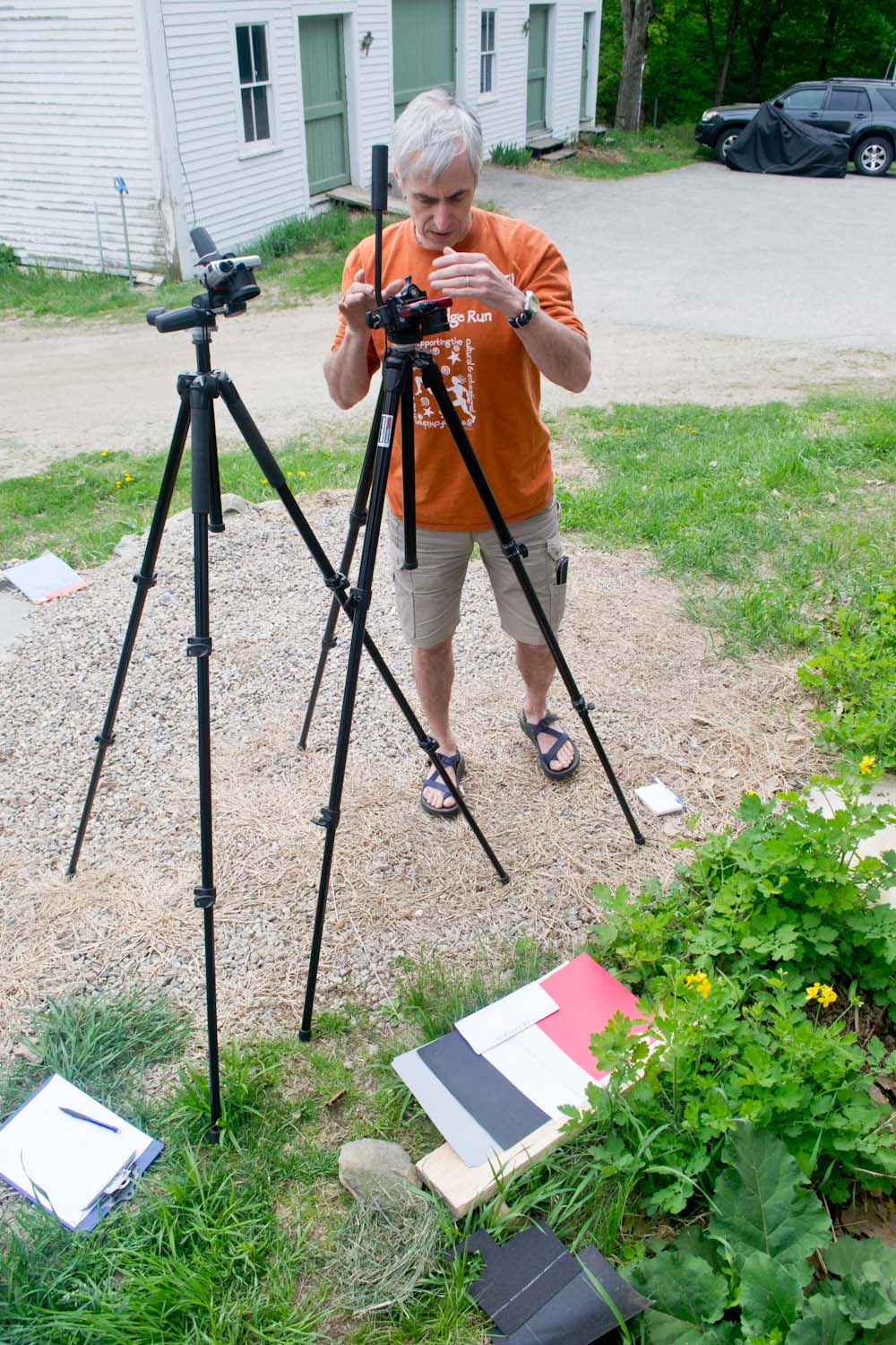
Note: The header image was acquired by by Chris Fastie and it shows the target layout for the tests.
11 Comments
Hi Ned - this is great. If you post the math, I'll try to port it to Infragram as well. Great work!
Reply to this comment...
Log in to comment
Hi Jeff - I'm not sure what math you are looking for. For the gamma correction I use:
The first step is to remove the effect of the gamma correction blueBand = blueBand ^ (1/blueGamma) #Where blueGamma is a user defined variable - I used 0.8 redBand = redBand ^ (1/redGamma) ##Where redGamma is a user defined variable - I used 0.8
The get the value from the test target I take the mean of the pixels in a rectangle that is drawn by a user
Next I remove the effect of NIR recorded in the red channel I use red = red - blue * percentBlue # Where percentBlue is the percentage of the blue band pixel value to subtract. I used 0.8
The last step before NDVI is to calculate the formula for the line (slope and y intercept) between the two points defined by the white and dark targets - y=the reference reflectance for the targets and x = pixel value after gamma correction and subtracting blue form the red. If there are more than two colored targets you could use a linear regression to get the formula for the line. The formula for the line is then used to predict reflectance and the result is used to calculate NDVI.
Does that make any sense? I can post my R script if that helps.
Ned
Is this a question? Click here to post it to the Questions page.
Reply to this comment...
Log in to comment
I'd love to see the R script. How do you recommend people select a value for redGamma or percentBlue?
Is this a question? Click here to post it to the Questions page.
Reply to this comment...
Log in to comment
Very helpful Ned, thanks! I'd also appreciate seeing your R script.
Reply to this comment...
Log in to comment
Hi - I actually thought I posted this a few days ago but for some reason I guess it didn't work. Now when I post it I see that the comments are interpreted as markdown syntax so pasting the code here doesn't work. I posted the script to our server and you should be able to access it by going to: https://resources.cbc.amnh.org/cbccloudstorage/index.php/apps/files/?dir=%2FR_scripts. The password is calibrate.
That R script is the one I used to calibrate JPEG images. This is a work in progress and not really refined enough for broad public use but I'm happy to field questions or take suggestions.
Is this a question? Click here to post it to the Questions page.
Reply to this comment...
Log in to comment
Hmm, I think I need a username too?
To post formatted code, you can use four
`characters --````on lines before and after your code, and it'll display in a "code" block.// Like this!You could also post it on https://gist.github.com and paste the link or embed in here.
Thanks, Ned!
Is this a question? Click here to post it to the Questions page.
Reply to this comment...
Log in to comment
I posted it on GitHub GIST: https://gist.github.com/nedhorning/f384d9afcc043741def3
Reply to this comment...
Log in to comment
Each
````has to be on its own line, then it should work. Thanks, Ned!Reply to this comment...
Log in to comment
@nedhorning Hello Ned thank you for posting the R script. I'm finding it helpful to understand the process by going through the script itself. I was wondering if the CSV file with target reference spectra is the same as the table you posted on "Improved DIY NIR camera calibration" from May 1, 2014?
Is this a question? Click here to post it to the Questions page.
Reply to this comment...
Log in to comment
The CSV file for the R script is different form the table in the "Improved DIY NIR camera calibration" post. The CSV file has the reflectance value for even wavelengths from 400nm to 2498nm as rows and two runs each for the 6 sample targets. I can send you the file but it would only work if your targets were identical to mine. The best solution for you is to edit the R script to only read the specific reflectance values for your targets that correspond to the center wavelengths for each band pass for your filter. You would store those values in the "refVis" and "refNIR" variables.
Reply to this comment...
Log in to comment
Okay thanks Ned! I had been wondering about the structure of the csv file since, judging from the script, it had quite a few columns of information in it. So now it makes sense since you did two runs and would have had at least 12 columns then.
Reply to this comment...
Log in to comment
Login to comment.