This is an update to the main project: Horticultural Spectrometer Upgrade - Planning.
Recent accomplishments:
- Acquiring most of the hardware parts
- Setting up the Raspberry pi to interface with the computer over USB and successfully viewing the camera output on the raspberrypi.local/html web address.
This article describes the fun part, hardware assembly!
For the most part, I followed the steps in Assembling the Public Lab Lego Spectrometer until I found out my pi NoIR camera was oriented differently, so I had to alter the lego structure. See all steps below:

1. Confirm Pi Zero W and Pi NoIR camera are successfully set up to be "plug and play" with the computer
This step was extremely important for me, as I didn't want to be fiddling around with the SD card or the pi, or the camera after it was set up inside the spectrometer.
 2. Layout lego pieces
All the pieces are organized and in the correct number. Great!

I also cleaned each individual lego piece with a brush to minimize the amount of dust that would get locked into the spectrometer. Any dust inside the housing could later end up on the diffraction grating or camera lens, or even the slit, which would be undesirable.

3. Assemble the lego, glue in the camera
With the first three layers assembled, I used gorilla superglue dabbed around the camera breakout (not on the electronics parts! Just around the edges near the screw holes and on the back of the camera connector, which has a big flat piece of plastic). Little did I know I'd soon have to pry the camera off due to this camera having a different orientation!!

4. Focus the camera
To focus the camera, I first cut a piece of card the same length as the distance between the camera lens and the front of the spectrometer, where the slit would go. That's because I ultimately wanted to focus the camera on the slit.
Then, I used this piece of card to align a picture directly ahead of the camera, using a metal arm device. The idea was that if I focused on the photograph, it should be akin to focusing on the slit since they are the same distance from the camera (just that the diffraction grating redirects the light from the slit into the camera from a different angle).

I focused the lens using the little plastic tool that came with the pi NoIR.
Here you can see the screenshot on my computer of the before and after:

5. A big problem with the camera orientation!
It was here that I started realizing something was wrong. In real life, the public lab image was upright, but in my computer, it was upside down. I expected it to be sideways. Being upside down, it meant that the diffraction grating was going to deflect the spectrum from bottom of the camera sensor to top, not left to right. I consider this to be a major error, as due to "rolling shutter", the camera reads data from the sensor in horizontal lines one at a time. It is MUCH more strategic to have the entire spectrum readable from one single horizontal line.
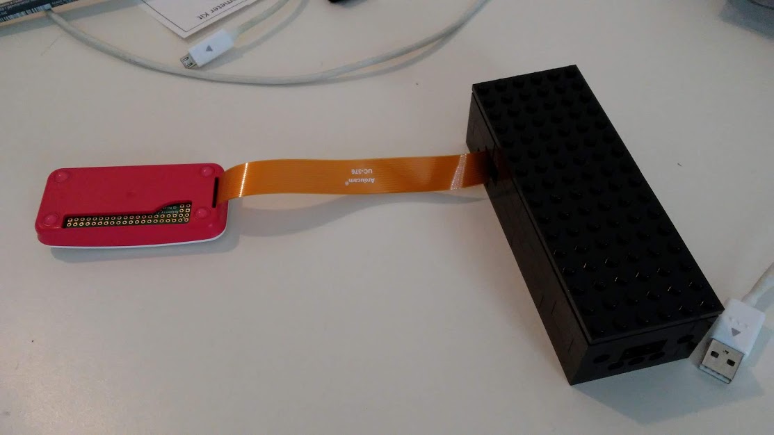
I had to now rip off the camera from the plastic and make the cable come out the side of the spectrometer.
This is how the modified version looks:

Parallel to this, I prepared the diffraction grating:

6. Diffraction Grating
I used the thin diffraction grating film provided by PublicLab rather than the DVD. First, I dug through my recycling bin and found a very stiff clothing tag to become the frame for the diffraction grating. With a knife I cut it into the correct dimensions with a small hole just big enough to fit the camera lens.
Being very careful to only handle the gratings by the edges, and only place them on clean, dust free surfaces, I cut them into pieces with scissors.

I chose the cleanest piece with least visible scratches/dust, and taped it onto the card frame. This I had to attempt twice, to try to get it as flat as possible. The film warps easily, and I didn't want that negatively affecting my measurements.

When I hold the grating up, you can see the reflection of my window blinds. It should be perfectly straight, but it's not. That's because the diffraction grating is a bit warped, but it was the best I could do.

7. Nearing final assembly
Here the build is nearly complete. I've put in the black card to prevent reflections, but I still haven't put in the slit. I also haven't fixed the diffraction grating in place. That was a lot of work for one day and I'll finish this post when it's done.
For now, I checked on the camera feed to see what the spectrum looks like, just from light coming in the window. For having no slit, I'm pretty happy with it and I hope it will look better when the slit is in place. Time to go buy some razors...

Update:
The next steps can be found at Horticultural Spectrometer - Assembly II
9 Comments
Looks like a nice clean construction. The glue should help mechanical stability. I did notice the swap from DVD to what appears to be a film holographic grating -- as you noted it was "warped". I'd suggest two things: 1) discover the lines/mm, compare that with a DVD and run the numbers for the impact on the diffraction pattern, and 2) investigate the mechanical aspects of using such a film.
Remember, the diffraction optics are relative to the wavelength of light so the accuracy of the diffraction pattern is dependent on collimated light passing through parallel grating lines (which, with the film, are not guaranteed parallel). [There is a 'band of illumination' of many grating lines which all contribute to the diffraction pattern. The slit approximates collimated light, adding a little error, but a non-planar grating could cause significant distortion.] Recall that the grating works by creating an interference pattern which varies with wavelength so wavelength-size surface anomalies can cause significant distortion to the interference pattern and thus the detected spectrum. It also thus follows that rigid mounting of the grating is directly related to spectral stability -- especially in terms of measured wavelength vs calibrated wavelength for any given specific camera pixel. ... there is also the issue of mechanical shift of a thin film due to temperature change which is probably significantly greater than the more rigid DVD substrate. True, the DVD is not an ideal grating and it has curvature to the lines but at least it is relatively flat and rigid.
Also, recall the diffraction formula: diffraction angle = asin(L/d) where L=wavelength of incident light and d=grating line spacing. So the line spacing will determine the diffraction angle which impacts the wavelength-change per pixel spectral resolution at the camera. DVD vs film line spacing might be quite different.
Thanks for the feedback, and for the equation. That's super helpful. I asked the PublicLab when I ordered my kit regarding the diffraction lines/inch and they didn't have the information. But based on looking online for diffraction grating films, I haven't seen grating film commonly available other than 500 - 1000 lines/in, so it's probably safe to assume it's within that range.
I'm almost done with the slit, and then before I permanently install the diffraction grating I think I'll do a comparison between the DVD and the film, since I have both handy anyways.
I'm also trying to think if there's a better way to mount the diffraction film, because I don't like seeing the warpage and I'm thinking that scotch tape is not really a sturdy solution for long term.
I am leaning towards the holographic film because it probably has less stray light and probably absorbs less UV due to it being so thin. But still it will be great to have an actual side by side comparison.
A while back I experimented with some 35mm 'slide-mount' holographic grating film (I believe it was 1200) vs the DVD (which is 740). The diffraction angle difference can be significant (a more 'compressed' spectra for the film so lower resolution at the camera in terms of 'nm/pix'. Anyway, I found the film quite difficult to achieve sufficient mechanical stability. You could try compressing it between two glass microscope slides if you could find a way to maintain the compression force as a constant. Direct contact would help reduce the glass-air-film-air-glass transitions.
As I recall, I looked at the transmission characteristics of both the film and the polycarbonate of the DVD and concluded that, relative to the limits UV sensitivity of the WEB cam (drops to near zero at about 420nm) the thickness and material didn't matter.
My guess is that making the spectrometer housing light-tight is way more important than any incidental refractive-based issues at the grating due to film vs DVD.
So, 1) rigid optical path (slit-grating-camera), 2) light-tight and 3) totally opaque slit material with very sharp very parallel edges.
Yes, so far I'm trying to accomplish all those 3 points. As for the slit, I made it from a razor blade so it should fulfill the criteria. I compared it with the acetate 0.09mm slit and it's a relatively similar width (just a visual comparison after taking a photo).
I'm curious regarding the lines/cm of your previous tests, because according to the equation (diffraction angle = asin(L/d)) you mentioned, a greater # of lines/cm should mean a wider spread. Correct me if I'm wrong, but I think maybe it was the DVD that had 1200 lines/cm and maybe the film had ~740; that should have resulted in the DVD causing a wider spectral spread.
I'm interested to see how my grating and DVD compare.
As for a better mounting for the holographic film, I'm toying with the idea of sandwiching it between two metal washers, and having some way to clamp them together. But I think I'll sleep on it and see if there are any other ideas that come up.
Also - I like the idea of microscope slides, except that glass strongly absorbs UV <400nm. I'm not sure of how well the pi NoIR is on that range but for now I'd rather have as little material in the optical path as possible. I haven't tested out UV yet at all, since I only measured light indoors and the sunlight through my window should be pretty depleted of UV due to the glass.
^^^ I just realized you were referring to line spacing in microns, not lines/cm! Now it makes sense.
Right ... the optical distances are very small ;-) which is why mechanical rigidity is so important ... (think of the 'optical bench' which is made from a block of granite).
On the issue of glass ... I'd thought that microscope slides are typically borosilicate glass which has a UV '90% transmission knee' at about 300nm (effectively 100% at 400nm and longer wavelengths) while the NoIR camera sensitivity is down to near zero at 350nm. So, a 50-mil thick slide seems unlikely to have a significant impact on the web-cam's own UV limitations. Also, obtaining useful camera pixel data below about 20% sensitivity of saturation (as in anything below 390nm) will often be swamped by noise. Just a thought.
I just looked up the transmission spectrum of borosilicate glass and you're right I think it's fine. I might just try the microscope slide idea. I did some tests with the new slit, and I can see that the spectral spread is not perfectly straight. It might be because the grating lines are not parallel with the side of the camera sensor, and also it could be slightly warped.
Progress. Right, the likely alignment issue is grating to camera which is notoriously hard to do without having much mechanical control beyond tape. Camera body and the slit are easier to align to the housing -- if both are rigid then the grating becomes the primary variable.
Viewing the spectral image as side-to-side, that line of camera pixels will be 'vertical' in the camera with the grating lines 'horizontal' like the slit. So, the slit 'length' need not be very wide as it only contributes to a 'taller band' in the viewed spectral image. The most accurate spectral 'line-of-pixel' data will be aligned with the optical center of the camera lens. Nothing new here, just a target point for adjustment. With DVD 'gratings', it's important because even at the DVD edge, the grating lines are curved so the viewed spectral 'band' needs to be both 'centered' and have no offset angle.
Reply to this comment...
Log in to comment
Login to comment.