
I used the 3D printed mini spectrometer from @rthalman and made some changes to improve performance and ensure it would serve my purposes well. The parts simply need to be printed on a consumer-grade 3D printer and cleaned as is typical for each specific printer model. I used methylene chloride to solvent weld the phone case to the grating holder, but this is not strictly necessary as there is a peg and hole combo that holds it all together reasonably well. In the exploded view of the pieces below, you can see how each piece fits together. Otherwise, the parts simply slide together as shown.

From left to right: flashlight cradle (blue), flashlight adapter (dark grey), universal cuvette holder (orange), cuvette mockup (clear blue), cuvette cover (black), slit tube (light grey, as produced exactly by @rthalum), tube adapter (light blue), grating mount (dark blue), phone holder (green, for iPhone 6s and modified from a design made by Quentin MAURIN on Onshape.com)
The figure below is the first print of this system:
On the left end of the universal cuvette holder you may notice a small slot, this is for a piece of white paper or similar to serve as a gain filter. The grating mount takes a 1000 blazes/mm grating mounted in a standard projection slide (2 inches x 2 inches). I purchased my grating on Amazon.com in a pack of 10 for roughly $10.
It is worth noting that I have already modified the design to flip it 90 degrees and make the use of the phone a bit more comfortable. See figure below:

I have not yet printed this configuration, but am excited to see it come together. While I was working on this I realized a simple modification to the flashlight adapter would allow for a 90 degree signal geometry, which could theoretically be used for fluorescence. See figure below:
In this configuration, the signal enters the cuvette from the side of the instrument and signal is collected as before.
Here is one of the images I was able to collect with the horizontal system:
And here is one crudely collected by rotating the apparatus 90 degrees to the vertical configuration and then taping the flashlight adapter to the end. Call it a proof of concept.
The black streaks in the image are likely due to the use of a completely plastic printed slit. I intend to modify this design to include a slit made from two razor blades and will report back when I have accomplished this. In the meantime I will utilize the row averaging feature of SpectralWorkbench to help compensate for fluctuations. Additionally, I plan to use the same rows of data each time.
Perhaps I should have started with this, but the initial rationale for designing such an instrument was my imminent study abroad course in Ecuador including the Amazon rainforest, the high altitude cloud forest, and the Galapagos islands. I am working with an undergraduate student to develop a crude study of the soils in each location. We plan to test the ability of unamended and biochar amended soil in the capture of several food colors (these will serve as admittedly poor analogues for organic decomposition products). This instrument and SpectralWorkbench will be used in the analysis of the collected spectra, but you'll have to wait for the data as we don't leave until early January and will not return until late January 2019.
Thanks for taking a look!
22 March 2019 Update: We were able to use both the visible spectrometer and the fluorimeter in the Amazon, but we planned to use an iOS device as the detector (iPhone 6s) and that interface with spectralworkbench seemed to be buggy. We were able to collect the images without any issue, but uploading them to the spectralworkbench archives proved to be impossible especially with spotty internet in Ecuador. We were, however, excited to discern visible differences in the water samples we ran through several soil columns and we were delighted to see visible signs of fluorescence using a blue LED to excite chlorophyll extracted with ethanol from leaf cuttings. There was a strong and unique signal in the red region as expected.
Upon returning home to St. Paul, I set about improving the design and addressing the software issues. I had initially wanted to integrate the iOS devices as a way to allow users to bring their own device and thus simplify, but that has not worked well. I have seen the software work better on Android devices, but don't own one and can't test it. In the end, I opted to integrate a USB ELP camera I purchased on Amazon instead. This interface appears to work much better with SpectralWorkbench. The STL files are linked below. Other changes include removing the slit from the printed slit tube and using either metal foil tape or a LASER cutter to make slits in cardboard, there is a slot in the slit tube to insert the slit, but the old slit tube can still be used instead. Additionally, there is a small cradle designed for an optical filter to be placed between the cuvette and the slit, this is designed for 1" optics, but optics need to be placed in the cradle. Let me know how it works and please suggest changes.

CAD image of the updated 3D-printable spectrophotometer with USB ELP camera mount.
Picture of the 3D-printable spectrophotometer with USB ELP camera installed and with new flashlight/fluorescence adapter combo along with LASER and LED penlights used for excitation.
Here's the original STL print files (in inches):Flashlight_Adapter.stl, Cuvette_Cover.stl, Flashlight_Cradle.stl, Fluorimeter_Adapter.stl, Grating_and_Phone_Mount.stl, iPhone_6s_Case.stl, Slit_Tube.stl, Tube_Support_Bracket.stl, Universal_Cuvette_Holder.stl
Zip file with original STL files in mm:Original_STL_files.zip
Here's the updated STL files as of 22 March 2019 (in inches):Universal_Cuvette_Holder.stl, Camera_Base.stl, Flashlight_Cradle.stl, Camera_Lid.stl, Cuvette_Cover.stl, Flashlight_Adapter.stl, flashlight_cap.stl, fluorescence_cap.stl, Grating_Mount.stl, Slit_Tube.stl, Tube_Support_Bracket.stl
Zip file containing all of the 22 March updates in mm rather than inches:Updated_spec_in_mm.zip
7 Comments
I made this! The print took about 36 hours and Amazon sells $12 diffraction slides. The .stl files aren't scaled properly when imported to Cura, but using a 25.103 multiplier seemed to work accurately enough. What emitter do you recommend for the fiber optic excitation adapter? The flashlight adapter works well but I would like to buy the fiber optic excitation method for a wider range of excitation. The design printed well and I recommend using raft and support "everywhere" for thermal extrusion printers. Thanks for this awesome design and lemme know what excitation you recommend!
Is this a question? Click here to post it to the Questions page.
Reply to this comment...
Log in to comment
I did this! Use 25.103 as the multiplier to scale the .stl file to the proper size in Cura and also the diffraction gradings are available on Amazon for $12. The print took me about 36 hours for 30% fill. The parts all fit snug and are well designed to reduce noise and light interference. Thanks for the awesome design and what fiber optic excitation instrument do you recommend for the, "In this configuration, the signal enters the cuvette from the side of the instrument and signal is collected as before."?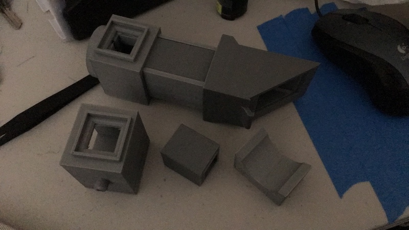
Is this a question? Click here to post it to the Questions page.
Reply to this comment...
Log in to comment
I did this! Use 25.103 as the multiplier to scale the .stl file to the proper size in Cura and also the diffraction gradings are available on Amazon for $12*. The print took me about 36 hours for 30% fill. The parts all fit snug and are well designed to reduce noise and light interference. Thanks for the awesome design and what fiber optic excitation instrument do you recommend for the, "In this configuration, the signal enters the cuvette from the side of the instrument and signal is collected as before."?
*UPDATE 25.103 is about 2-3mm too small for the iPhone 6S. Am testing a slightly bigger multiplier and will post updated.
Is this a question? Click here to post it to the Questions page.
chunbr, thanks for you interest. I apologize for missing your comment and questions, I have been exploring some new adaptations to this system that have significantly improved the usability. As for the excitation source at 90 degrees, it was made for a solitary LED to be pushed into that hole, the wire leads of the LED can then be pushed against the terminals of a battery to produce the excitation. This worked well on ethanol extracts of chlorophyll in the Amazon this past January, but the web interface for iOS was not working well so we were not able to produce spectra from the images. I have since developed a mount and case for a USB ELP 8MP camera I purchased on Amazon. The spectralworkbench works much better with this. I will post the files and a picture soon. Also, a weird side affect of the way I generated the STL files is that the parts were actually designed in inches, but the STL files "think" they are in mm. The scaling follows that conversion exactly. I am able to do this with a software feature in my 3D printing software from Makerbot.
@realestateediary Are there any further updates to this design? Re the razor slit or any geometric changes? I am very much interested in printing this design in a more updated form? I have several Lazer pointers, which I plan to use red, green and violet. Best Stef, Is.Chowa@ @gmail.com
Is this a question? Click here to post it to the Questions page.
Stef, thanks for your interest, I have some new updates and they can be found in this open-source publication: https://doi.org/10.1016/j.ohx.2021.e00232
Reply to this comment...
Log in to comment
If you are interested in getting access to the original CAD files, they are available for use on www.onshape.com under the file name "Visible Spectrometer".
Reply to this comment...
Log in to comment
Login to comment.