What are we trying to see?
For a full overview of this project, go to Raspberry Pi Microscope Build.
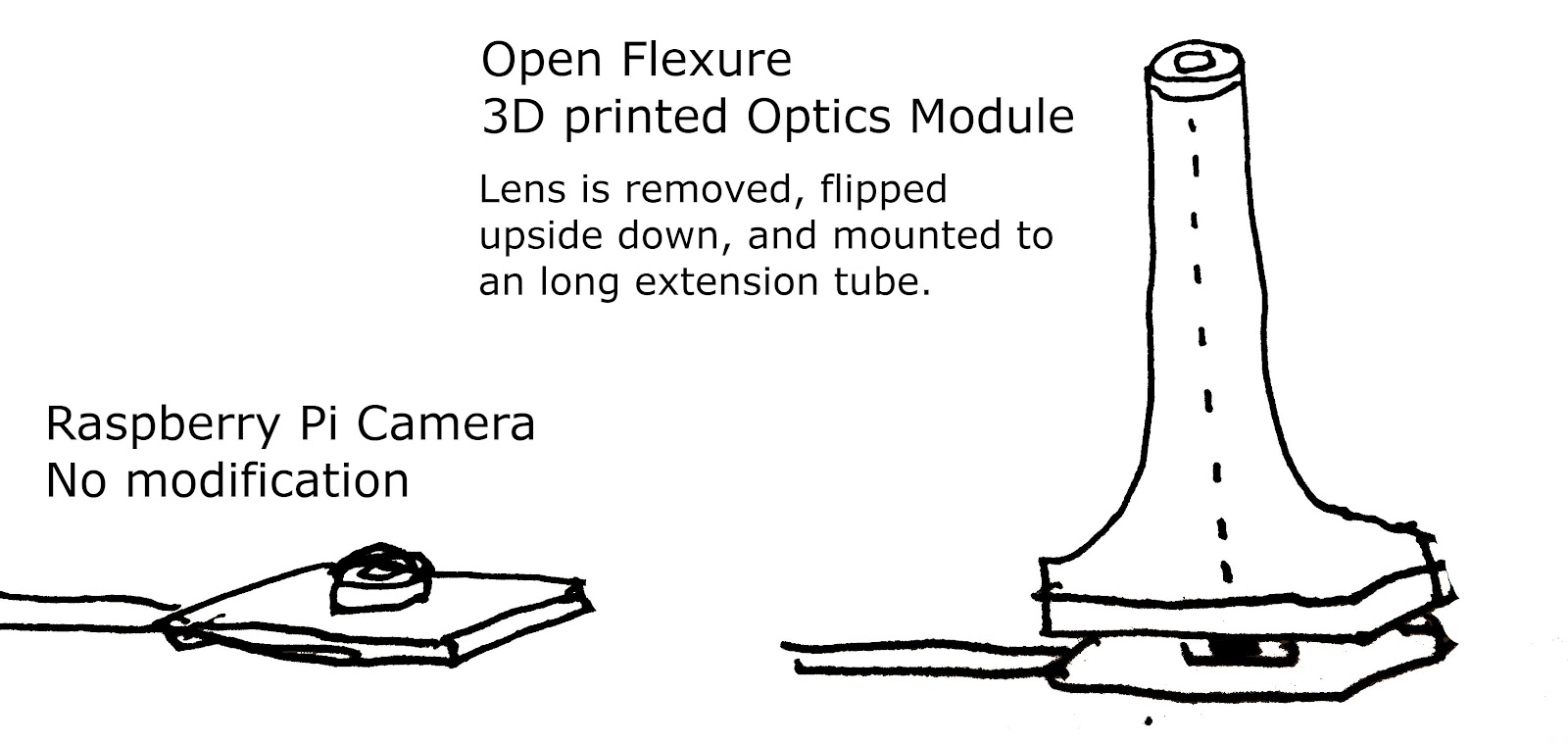
Our goal in this microscope project is to be able to look at and identify respirable particles with diameters between 1um and 10um. Most DIY digital microscopes that we've found are made by flipping the lens from a camera and holding it further away from the sensor using an extension tube of some kind. The Open Flexure Microscope uses this method.
This is a technique that's also very common in macro photography. With normal photography you are trying to project the image of a large object on a relatively tiny sensor. With microscopy and macro photography we are doing the opposite -- projecting the image of a very tiny object on a comparatively large sensor, so we just need to reverse the lens.


This flipped-lens technique works reasonably well and can give us images that are in the size range we're looking for, but if we want to be able to identify particles by shape we believe we will need better magnification that we can get from a traditional microscope objective lens.
Why Not the OpenFlexure Microscope?
The OpenFlexure microscope is an extremely high quality DIY digital microscope that we have based a lot of our designs on. This project should be studied and considered by anyone interested in DIY microscopy. Given the existence of this project, why are we making a new Raspberry Pi Microscope design?
We found that the process of building the OpenFlexure Microscope was difficult and daunting for even relatively experienced builders and tinkerers. A well-built OpenFlexure microscope is an incredibly robust and precise tool with features that our design does not have (finer focus and a movable stage). We feel that some of this quality and precision comes at the cost of a significantly more complex and difficult build process and that there is room for and value in a more beginner-friendly, easier, somewhat less powerful project.
Remixing the Open Flexure optics module with Hackteria stage
Adding a traditional microscope objective
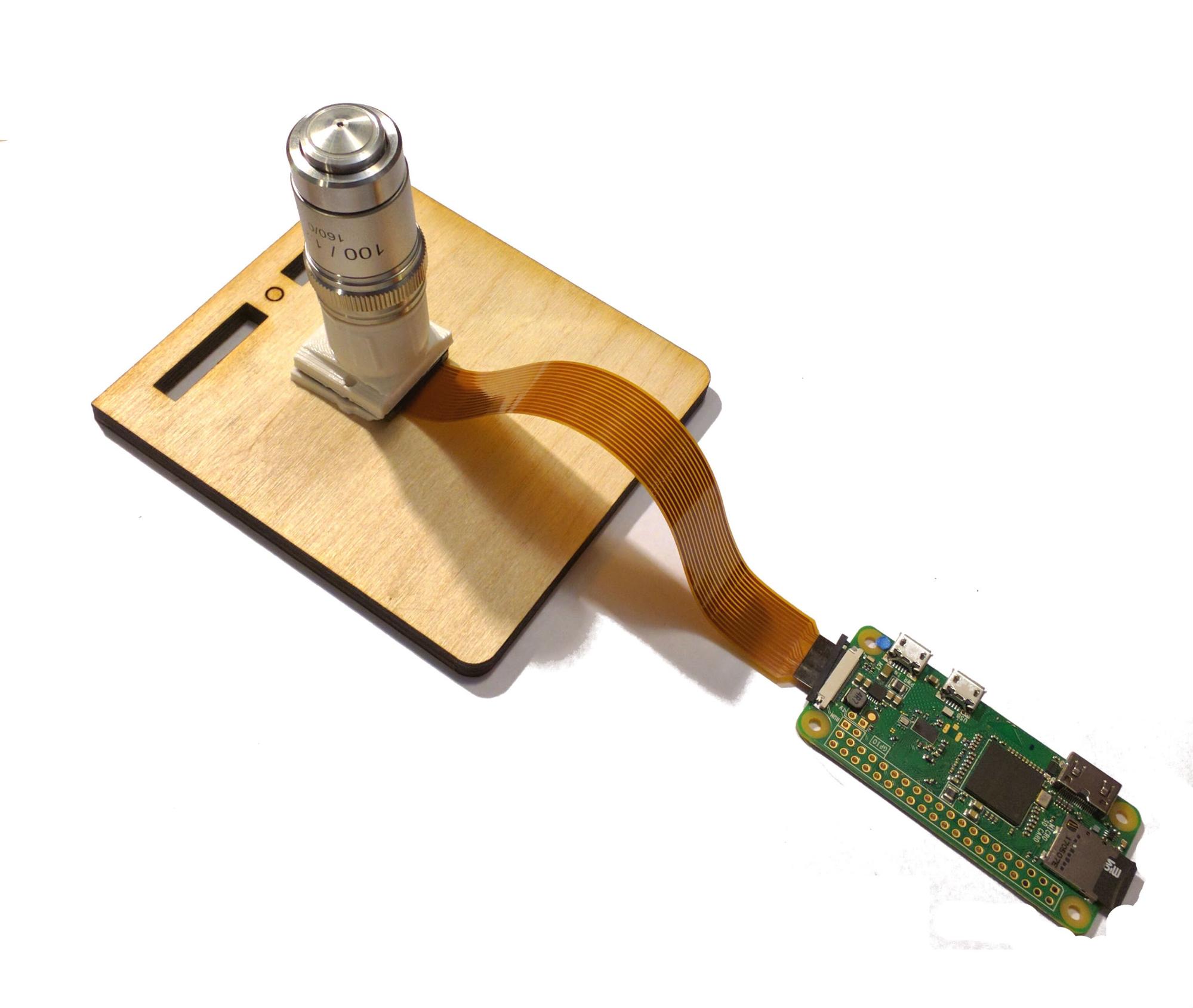
This microscope uses a Raspberry Pi camera as the sensor to capture images and send them to a computer for processing. We use a 3D printed optics tube for a 60 mm objective from the Open Flexure project. Everything is mounted to the frame from the Hackteria microscope stand.
How to Set Up Your Optics
Step 1: Setting up the camera:
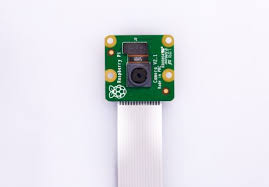
We use a Raspberry Pi camera (v2) attached to a Raspberry Pi Zero W computer to stream our images and take photographs/videos. The Raspberry Pi Zero W is a very small computer with built-in WIFI and bluetooth capabilities and the camera is an 8MP digital camera.

Wikimedia Commons www.raspberrypi.org
We use this camera+computer setup because our research suggests that this is one of the more suitable digital camera sensors available at this price-point (because it is a high resolution sensor that is physically quite small) and because there is a lot of already existing work in DIY microscopy built around the Raspberry Pi camera for us to build from.
See also: Setting Up the Raspberry Pi and Camera for Wireless Streaming
Step 2: Choose a microscope objective
Because we are trying to make a low-cost device, we are using the cheapest objective lenses we could find from Amscope -- http://www.amscope.com/accessories/objective/100x-oil-achromatic-microscope-objective-for-compound-microscopes.html. You can use either the 40x or 100x objective for this project.

These lenses are "RMS Threaded", which stands for "Royal Microscopy Society" and is the most common threading for microscope objective lenses. To mount the lenses onto the Raspberry Pi we use a 3D printed adapter modified from a design created by the OpenFlexure microscope project -- https://github.com/rwb27/openflexure_microscope
Step 3: 3D print the tube
To attach the lens to the camera, we use a 3D printed part based on this design from the OpenFlexure project -- https://github.com/rwb27/openflexure_microscope/blob/master/stl/optics_picam2_rms.stl
This model is an adapter that snugly fits the Raspberry Pi camera in the bottom, facing upwards into a tube that you can screw RMS threaded microscope lenses into the top of.

It's worth exploring the Open Flexure github page if you want to experiment with different tube lengths. Our version -- http://partsandcrafts.org/pi_microscope/optics_modified_partsandcrafts.stl -- is modified so as to have a shorter tube length and to remove some extraneous elements that are designed to interface with the rest of the OpenFlexure build.
Why A Shorter Tube?
We don't know right now! The lenses that we are using are specified to have a tube length of 160mm. The microscope stand is much smaller than that, so the OpenFlexure tube file is designed to fit an additional lens to correct for this shorter distance. More detail about this, as well as other magnification and resolution issues is available here --
https://github.com/rwb27/openflexure_microscope/wiki/Magnification,-Resolution,-and-Field-of-View
By shortening the tube length we are decreasing the amount of magnification we're getting out of the objective, but maybe this decrease in quality is worth the additional ease-of-use. The OpenFlexure project has you place an additional lens in the tube to correct for the shortened length. This method seems to work, but we've actually had perfectly good success using an even shorter tube then the one they use without any kind of corrective lens at all. More experimentation with tube lengths and lenses will help us find an ideal combination.
We found this tube length through trial and error experimentation, so don't have an explanation as to why it works well, but the initial results are somewhat promising so it's a good starting point for further experimentation.
Adding an additional quality lens to the project increases the cost by about $25, which isn't an enormous amount, but is enough of a price increase that I'd rather consider it an optional upgrade if the performance with the shorter tube and no lens is adequate.
Even so, this is a big area of open questions for the project and we would love insight into the following:
- Is there an "ideal" tube length to use without a lens?
- What are the advantages of having an additional tube length correcting lens?
- Is there an adequate cheap lens available to use for tube length correction?
- Is there an "ideal" combination of tube length and correcting lens? What happens when we increase/decrease the tube length? What happens when we increase/decrease the focal length of the correcting lens?
Design Files
We based our designs for the 3D printed tube and camera holder on the OpenFlexure designs. The OpenFlexure project provides a wonderful set of well-documented OpenSCAD files that generate all of the pieces of the project for 3D printing. We modified these OpenSCAD files to produce our 3D models in the following ways:
- We found that the bottom of the Raspberry Pi Camera cover didn't quite fit the ribbon cable so we removed a bit of material to make enough space for it.
- We removed the dovetail on the side of the tube which was designed to hold an illumination stand because we decided to use a separate light to illuminate the sample.
- We increased the size of the holes for bolting the camera to the holder + baseplate to fit the bolts we are using
- We shortened the tube to move the objective closer to the camera sensor (as described in the section above)
The 2 OpenSCAD files that we used are "optics.scad" and "picamera_2_cover.scad" We modified them in a very haphazard "make changes and see what happens" way, so these modified versions aren't the best, but they are doing the job for now. Our modified versions are labelled "modified" and the changes are somewhat documented in the .scad files.
Because these files reference other files in the OpenFlexure openscad folder you should downlaod the whole zip file which contains all of the files including the ones we modified. This file also contains the 3d printable lens remover tool.
http://partsandcrafts.org/pi_microscope/openscad.zip
These OpenSCAD files can be used to generate 3D model files (.stl) for 3D printing. These files are here:
http://partsandcrafts.org/pi_microscope/optics_modified_partsandcrafts.stl
http://partsandcrafts.org/pi_microscope/picamera_2_cover_modified.stl
http://partsandcrafts.org/pi_microscope/picam2_lens_gripper.stl
http://partsandcrafts.org/pi_microscope/picam2_lens_remover.stl
Build It!
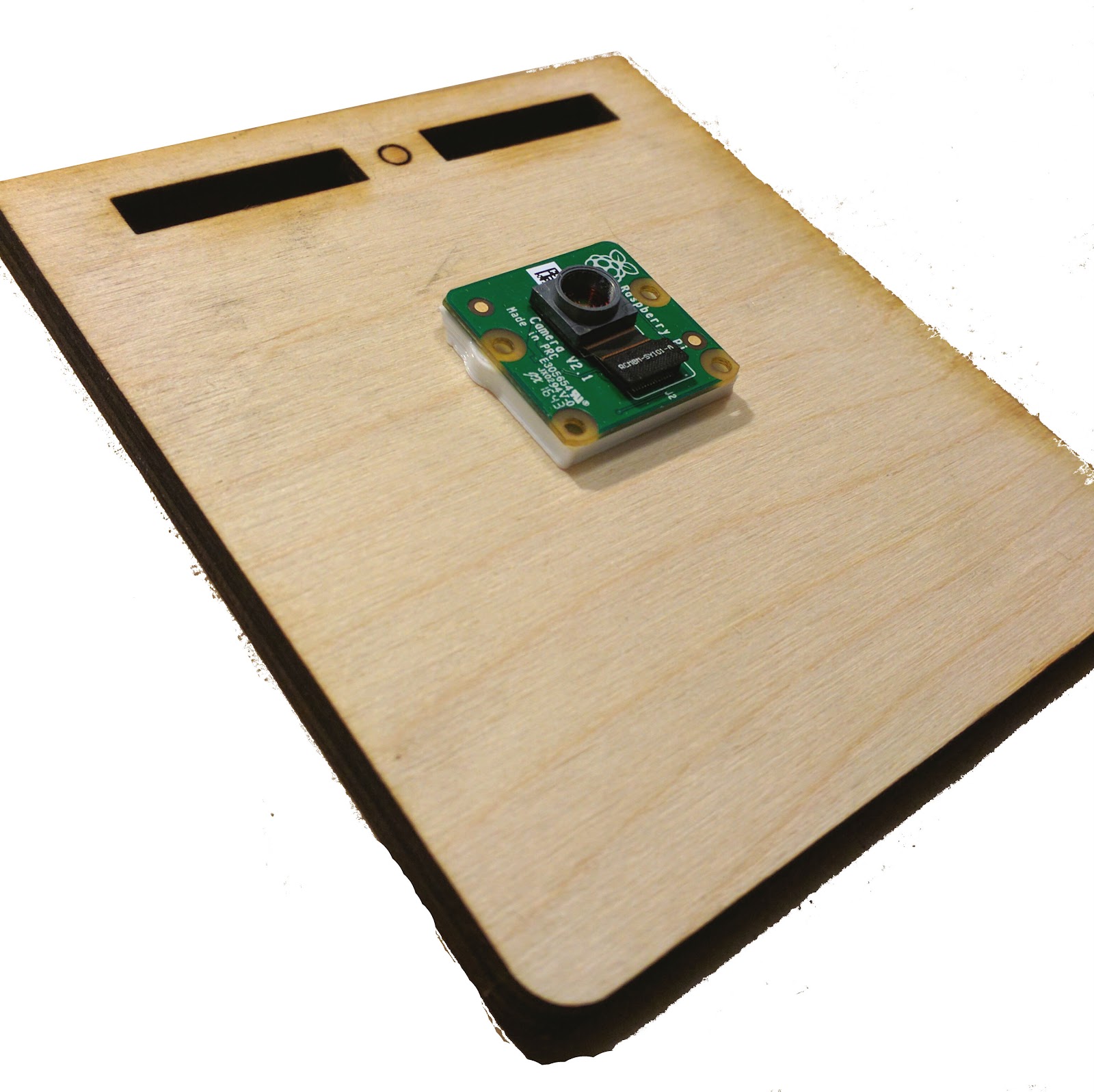
To attach the lens to the camera you need the 3D printed camera holder bottom, the 3D printed camera holder/tube adapter, the Raspberry Pi camera v2 itself, and the baseplate of your microscope stand.
1. Remove the Lens
In order to remove the stock lens from the Raspberry Pi camera, you will also need the 3D printed lens removal tool or a pair of pliers and a very steady hand.


The lens removal tool fits around the lens in the Raspberry Pi camera, and with a small amount of force you should be able to unscrew the lens and remove it, exposing the sensor. Once the sensor is exposed you need to be very careful not to get dust on it -- any dust on the sensor will show up on and mess up your pictures.

2. Attach camera holder base to baseplate
You will want your camera firmly attached to the baseplate of your microscope so that it doesn't move around at all when you adjust your sample or your focus. To do this we use 2 16mm M3 bolts to bolt the 3D printed camera holder bottom to the baseplate.


3. Attach the camera to the camera holder
The Raspberry Pi camera has 4 holes drilled into the PCB that you can use for mounting it. We will use the two middle holes which should line up with the bolts in the camera holder bottom and baseplate. One side of the camera holder bottom has an angled edge and a wall cut out for the ribbon to come out of. Make sure that the slot for the ribbon in the camera is lined up with this side.

4. Attach tube to camera + holder
The bottom of the tube contains a cut out section to snugly fit the Raspberry Pi camera. Place it over top of the camera and screw it into place.

5. Plug it all in
If you have not done so already, plug the camera into the Raspberry Pi and the Raspberry Pi into power. This is described in Setting Up the Raspberry Pi and Camera for Wireless Streaming

6. Attach an Objective Lens
You should be able to screw the RMS threaded objective lens of your choice into the top of the tube. Be careful to line the lens up so that it ends up being perfectly flush with the top of the tube. For initial tests we recommend a 40x objective.
7. Test it out!
If you have set everything up right you should be able to go to raspberrypi.local and see a blurry grey image from your camera. If you are careful and you are using a sufficiently small level of magnification (like 40x) you should be able to get an image just by carefully holding a well-lit slide just above the top of the lens and adjusting it to get it into focus. Keeping it in focus like this is obviously impossible, which is why we need to build the microscope stage next.
NOTE: The Quick Build instructions for this project have you attaching the optics and the camera in sync with building the stage. You may find it easier to build the stage with the objective unscrewed and the Raspberry Pi Zero W unplugged. If that's the case, back it up to Step 4 and start building the stage!
15 Comments
This is so great. I don't even have one in front of me, and I can follow along. Nice work!
if you're switching out the objectives, do you have thoughts on how to keep dust off the sensor?
Great questions on the "why the shorter tube" section, wondering if @warren has ideas on pulling those out for some sort of top level design challenge questions?
Is this a question? Click here to post it to the Questions page.
Reply to this comment...
Log in to comment
Hi, we're trying to use Raspberry Pi's v1.3 cameras, and the lens adapters don't fit the placement of cables and components on those, but it looks like the printed adapters could be made to fit both -- is that something you could help us with?
Is this a question? Click here to post it to the Questions page.
Reply to this comment...
Log in to comment
@wmacfarl @kgradow1 @bmela
Reply to this comment...
Log in to comment
@warren @kgradow1 @bmela It wouldn't be hard to print out adapters for the v1.3 camera instead of the v2 camera -- the way the OpenFlexure project designed the OpenScad files is really well-done and modular so you can just change the "camera type" setting in one of the configuration files.
Are you suggesting making a single adapter that fits either camera? This seems harder and less ideal than just printing two adapters, but it probably could be done....
When I was working with the v2 camera and an adapter designed for the v1.3 camera (the opposite problem you have) I was able to make it work reasonably easily with a knife and file, which isn't a long-term good solution, but it works.
Is this a question? Click here to post it to the Questions page.
Reply to this comment...
Log in to comment
Hi there, what a great project! I have a question, in a certain way related to your article. Would it be possible to connect or adapt your work to an existing "stereo microscope", quite old and I have been thinking to somehow connect to a camera or even a PC? I use it for particle size and shape analysis of sandstone, beach sand, soil fractions passing 60 microns. So far I have tried an application "Magnifier" which is ok to get some images at to about 20 microns. Anything smaller is not that clear.
Is this a question? Click here to post it to the Questions page.
Reply to this comment...
Log in to comment
Hey, nice work! I thought I'd chime in with some information about tube length in case it's helpful. You're right that most RMS microscope objectives are designed to produce an image 150mm from the "shoulder" where the thread joins the body (the 160mm "tube length" refers to a tube that accepts eyepieces, the image is nominally about 10mm from the end of that tube, hence 150mm).
A perfect thin lens will image an object on one side of the lens to a plane on the other side of the lens. If the distance from object to lens is a, and the distance from lens to image is b, then the magnification is b/a, and 1/a + 1/b = 1/f where f is the focal length of the lens. Normally a is quite a lot smaller than b, so if you change b a bit, you don't notice much of a change in a. That is the reason you can get away with a short tube length and still get a reasonable image.
However, microscope objectives are neither perfect, nor thin, nor lenses - they are usually made up of several lenses, and carefully optimised for one particular set of distances (the "design conjugates"). So, while you can vary a and b to change magnification, you need to remember that by doing this, you're using the lens in a non-optimal way. You will have the magnification you want, but the resolution (i.e. image quality) will be lower.
Adding the second lens means that the objective is being used more or less the way it was intended to be used, which does improve the image quality - though it's more noticeable for high-power (40x or 100x) objectives. Using an achromatic lens is best, but it's hard to buy those cheaply in any quantity - you can try to get hold of cheaper "singlet" lenses which are a compromise between price and quality. I think it might be possible to use lenses designed for Google Cardboard VR, which can be very cheap, but I've not yet put together an optics module that will work with these.
Oh, and the other nice feature of using a secondary lens is that it protects the sensor from dust, though I'd caution you that the plastic won't cope with repeated changes of the objective lens, eventually it will wear out.
Correct on the Cardboard Lens, I suspected the same after finding it very hard and expensive to get a openflexure tube lens. OpenLab has a scope that uses a cardboard lens, or very close to one, using a 50mm focal length where cardboard is 45mm (both 25mm dia) http://openlabtools.eng.cam.ac.uk/Instruments/Microscope/Optics/ They do not have 3d printed tubes. I am making a design once I find the correct position for the tube lens. Wrestling with using my picam v2 with the lens on so I can have it mounted on my printer, allowing me to switch between a printer cam or controlled microscope by just screwing on a lens. So far, I have had better luck with the M12 low refraction lens kept on.
Reply to this comment...
Log in to comment
Wow that's great information. Thanks for posting!
Reply to this comment...
Log in to comment
That's really helpful, thank you! I feel like I need to reread and synthesize this a bit, since I still have a very rudimentary idea of how microscope optics work.
We had a lot of problems with dust getting stuck on the sensor -- though my recollection is that the pixels on the sensor are themselves in the 1-2 um range (I'd have to look it up for sure) so it's sort of nice to just imagine it as a rough calibration of the fine particles you're breathing in the room as you're setting up the microscope. Poetic, but not perfect. You can see them all over our images.
Reply to this comment...
Log in to comment
Paquicamus, there are a number of adapters that are available through Thingiverse to connect the Raspberry Pi camera to a stereo microscope, for instance: https://www.thingiverse.com/thing:214466. I don't have good ideas for if / how this would improve resolution or magnification, but it would at least get it into a digital format.
We haven't done a lot of work on this part specifically, but it would be cool to try!
Reply to this comment...
Log in to comment
@kgradow1, you're dead right - the pitch of the pixels on the camera module (v2) is 1.12um so the fine particles do show up as little dots. Fun fact - if you use the right illumination (has to be relatively well "collimated", an LED held ~100mm away should do), you should be able to see rings around the particle. Those rings should let you calibrate the particle size very nicely, although given they are hard to remove from the sensor, it's an expensive single-use microscope!
I also had quite a few issues with dust on the sensor, that's why the optics modules are now single tubes - once the lens is in, the whole thing should be reasonably well sealed. I originally had the camera and lens on separate mounts, but that resulted in a lot of dust on the sensor.
Reply to this comment...
Log in to comment
richardbowman commented 5 days ago @kgradow1, thank you for your information and link. I will try and follow the directions. At the moment, I am only interested in getting a digital format and be able to apply and using another software for measuring sizes and shapes. Usually, I work with particles sizes from 10 to 62 micron, silts and fine sand. The Raspberry Pi Camera looks a very attractive possibility. Thanks.
Reply to this comment...
Log in to comment
Remember - you're buying an OIL objective lens.
This means it's been designed and built to use oil in contact with the lens and the cover-slip of glass the object to be viewed is under.
This is to get around the problem of refraction through the air limiting the magnification to around 800x (when using the relevant ocular lens).
You might find you get a better (sharper) result using a lower magnification tube, that doesn't need an oil layer - especially if you have no intention of using oil!
Reply to this comment...
Log in to comment
Hi, great project! I have a question, not exactly related to the raspberry pi microscope but I'm hoping you'd be able to help me out... I'm using a web camera with the similar flipped lens concept to build a microscope but the image has a huge amount of background noise... looks like the components of the chip are somehow projecting their reflection onto the image. Any suggestions?
Is this a question? Click here to post it to the Questions page.
Reply to this comment...
Log in to comment
Hi, this looks like a great project and I'd love to try it out. The 3D file links appear to be dead and produce a database error. Any chance anyone can forward me the files please? @partsandcrafts @warren @wmacfarl
Is this a question? Click here to post it to the Questions page.
Reply to this comment...
Log in to comment
Login to comment.