What I want to do
We want to calibrate our arduino-based conductivity meter to give true measurements of specific conductivity (in microsiemens per cm). Our current device measures conductivity on a qualitative level--adding ions to the water gives larger numbers; adding purer water gives lower numbers, but that's just not good enough.
My attempt and results
We used a temperature/ conductivity probe borrowed from a lab in the UMass CEE department. The idea was to take measurements using both devices--ours and the lab probe--for a range of conductivity. The steps were as follows:
- Beginning with cold tap water, measure temperature and specific conductivity using the lab probe, record measurements
- Remove probe, submerse our device, record measured temperature and uncalibrated "conductivity".
- Remove device, add a smidgen of salt, stir water until dissolved.
- Repeat septs 1-3 until a sufficiently large range of conductivity is measured by both devices.
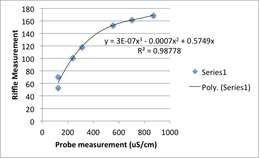
- Plot data, fit a curve describing the relationship and adjust computation in Arduino code.
Questions and next steps
The observed relationship between measurements from the two devices was strangely nonlinear. We wonder if this has something to do with the range of voltage measurements the circuit is capable of, given its configuration (e.g. voltage supplied, resistance of resitors used). Still, the data show a clear monotonic relationship that is well described using a 3rd-order polynomial function:

While this provides a great improvement in accuracy, further calibration will likely be necessary, particularly in the low conductivity range.
5 Comments
The PhotosynQ team is going through a similar process trying to find (or mostly likely just design our own) a conductivity meter to use with our MultispeQ. We had tried an off the shelf probe, but were unhappy with the results. What kind of hardware are you using (maybe we have some overlapping issues)?
Is this a question? Click here to post it to the Questions page.
Reply to this comment...
Log in to comment
The probe we're using is an accumet AP85 from Fisher Scientific. We're assuming this is working perfectly--admittedly it too should be calibrated. I've got access to calibration standards--the next step will be checking against these.
Reply to this comment...
Log in to comment
Do you mean that the probe you used for testing your device (borrowed from UMass CEE dept.) was the Accumet AP85 or do you mean that you bought the Accumet AP85 and have incorporated either just the probe, or the probe and meter into your arduino device? Specifically I am interested in the circuitry that you have your probe (the arduino based conductivity meter) hooked up to, and the probe itself. Is there a post about your work designing the conductivity meter? Perhaps it is this (http://publiclab.org/wiki/555-conductivity-meter) one? Thanks!
Geoff
Is this a question? Click here to post it to the Questions page.
Reply to this comment...
Log in to comment
We've been building a device based on the riffle, very similar in concept to the conductivity meter you've linked. We're using PVC pipe and our conductivity is measured using the resistance across two stainless steel screws. Our wiki needs some updating and cleanup, but you can find it here.
Reply to this comment...
Log in to comment
Just wanted to comment here if anyone finds this page, that there are new ideas about using lower voltage in the water and amplifying using an OpAmp to avoid electrolysing. Using even duty cycles will also help with calibration -- and increase the linear response range of the CT sensor.
https://publiclab.org/notes/donblair/01-07-2016/conductivity-sensing-open-questions https://publiclab.org/notes/donblair/09-18-2014/duty-cycles-555s-linearity
Reply to this comment...
Log in to comment
Login to comment.