Abstract
The PLab 3.0 Spectrometer is an entry-level device which allows viewing a visual-light spectrum. However, in keeping costs minimal for the user, some of the materials and construction techniques do not provide sufficient mechanical rigidity. This note describes a few simple, low-cost changes to substantial improve mechanical stability and improve measurement repeatability. Hopefully, PLab Kits can adopt and make this design available.
Concept
A spectrometer is an optical device which means critical dimensions are affected by nanometer mechanical changes. What this means is that results are easily affected by vibration, twisting, pressure and even handling. One of the primary causes for this as an issue for the PLab 3.0 (as of Sept '16) is that of the optical path. Vers 3.0 is made from paper, wood, velcro and tape. The optical path follows from the source of light, to the slit (which is mounted to the housing) to the DVD diffraction grating (which is mounted via velcro) to the camera (which is on separate velcro) and the wood base is not mechanically secured to the paper housing which holds the slit. Essentially, each component is free to move separately from each other component. Compare this with an optics lab where all components are mounted on a slab of granite. While using granite is obviously impractical, the PLab 3.0 design can be improved using very simple means.
Mockup
The design shown here is only a mockup, but it is based on a real design / build of a V3 prototype shown in these two links:
Original PLab-3 Spectrometer Upgrade Prototype
Adaptation of PLab-3 Upgrade Proto to OTK-upgrade proto
Construction of those prototypes is more involved than the mockup of this upgrade design but the underlying principles are the same -- to improve stability.
The design goals of this mockup were 1) improve stability, 2) simplicity, 3) low-cost parts, 4) utilize the existing paper cover (it's not very stable but it is relatively light-tight) and 5) allow the upgrade as a retrofit. The entire design, cut/sand parts and glue assembly only took 30 minutes to complete so building a retrofit should not be very difficult.
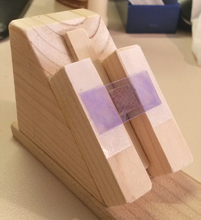
Photos
The mockup shows the same basic form-factor as the PLab-3 device such that it should fit inside the same paper cover. However, note the important changes where the slit mount, DVD and camera are ALL part of the same mechanical assembly where all component mountings are GLUED to each other for rigidity.

The slit mount allows for several options, including just taping the photo-film slit to a black paper "carrier"; which is then double-stick taped to the wood slit-mount. This is not the only option, but having the slit-mount glued to the base is important for stability.
[ Note that there are a total of five (5) new wood pieces. All are cut from 0.5 x 0.5 inch stock; four (4) of these are 2-in long but one (1) is only 1.5-in long as it sits across the width of the base (to align the two verticals of the slit-mount and for strength). ]

Note that the same wood pieces provide a mounting surface to double-stick tape the DVD in front of the camera lens. Yes, the DVD is placed at the same angle as the camera lens. See the following for observations on diffraction angles:
Observations on diffraction angles

Note that with a camera height of about 1/2-in, using 1/2-in square supports might be close tolerances for mounting the DVD. However, the addition of double-stick tape under the DVD would likely provide sufficient clearance. The exact distance between the camera and the DVD is not critical -- it should just be close and it should not move once it is positioned.
[ Note: The size of the 'square' parts is close to 0.5-in but the "ideal" value is set by the "height" of the camera lens after the camera is mounted. The dimension should be the same as the camera lens "height" or slightly higher -- as the double-stick tape to hold the DVD will add a small clearance. If, the mounted camera height were 0.5-in then the 'square' support dimension would be 0.5 -0.0 +0.125 . ]

13 Comments
I love this. I think white glue (EVA, like Elmers) is probably plenty good for this purpose, and most people will have some. But @abdul, I wonder if including a small bottle of white glue is not unreasonable; even on amazon they're ~$1, and in bulk i bet we could find them for much less:
https://www.amazon.com/Elmers-E1323-Glue-All-Purpose-Bottle/dp/B0044URT56/
Reply to this comment...
Log in to comment
Except ..... there is a real advantage of using the "yellow" "woodworkers glue", rather than white glue. "White glue" seems to be sold in different 'densities' (or so I've noticed) so I see that as an issue. More important, however, is the advantage of the woodworking glue (I used Elmers, nothing special) which is thick and sets-up very quickly -- literally within 30-60 sec with wood (which absorbs some of the moisture quickly) so that the parts won't keep "drifting" around after placement --- a real frustration for many. I admit, I've not investigated buying small quantities, but you might be able to buy small empty tubes or bottles and just provide small amounts from a larger supply. Sorry, but I don't think that common white glue is a good option.
Reply to this comment...
Log in to comment
Also, Dave -- a question: if people work to reproduce this, what are (in your opinion) the tolerances here? Could people make this with a different width square dowel than you've shown? Must it be the same dimensions -- to the, say, 1/16 of an inch? Or does it not matter, and how would you make that judgement? Thanks again!
Is this a question? Click here to post it to the Questions page.
Reply to this comment...
Log in to comment
The size of the 'square' parts is close to 0.5-in but the "ideal" value is set by the "height" of the camera lens after the camera is mounted. The dimension should be the same as the camera lens "height" or slightly higher -- as the double-stick tape to hold the DVD will add a small clearance. If, the mounted camera height were 0.5-in then the 'square' support dimension would be 0.5 -0.0 +0.125 . I'll add a note above.
Reply to this comment...
Log in to comment
Would superglue be acceptable?
The justification of superglue is outlined below:
-It dries quickly
-It comes already in small containers
-It is extremely cheap
-When purchased in bulk, it does not come in one massive container (which woodworking glue appears to), but instead comes in many small containers
Let me know if you think that it might be a viable option
Is this a question? Click here to post it to the Questions page.
Reply to this comment...
Log in to comment
Thanks, Dave -- I did a degree in architecture and so spent many a sleepless night gluing wood things together -- and I agree that not all glue is made equal. I personally use Elmer's Glue-all for all paper and wood work smaller than 1 foot or so in size, and it also sets in 30-60 seconds when properly used. I'm most interested in what's cheaply available in tiny bottles, and I'm sure we can test it out if we make this a kit variant.
Reply to this comment...
Log in to comment
@abdul, I'd not consider superglue because of it's negative properties for human skin -- a safety hazard. Remember, the kits are sold for educational purposes (kids). Wood glues of most types are pretty safe.
@warren, also remember that the total volume of glue required for a kit is actually very small so "small alternate containers" could be available. EG: ULine has 2-oz soft squeeze empty glue bottles for $0.75ea in quantity and you only need to fill them with 1/2 oz of glue. 1Gal of elmers yellow is $35 on Amazon so 250 1/2-oz fills would be $0.14 glue + $0.75/bottle < $1. Pretty cheap for the kit.
Reply to this comment...
Log in to comment
I like this idea -- you're right, even 1/2 oz would be plenty. Abdul, what do you think about that as an assembly step? Would one of those "push to dispense" tops on a wood glue bottle be a pain to use to fill a few dozen or more at a time?
We're doing a build of this at #LEAFFEST2016 now... will post more soon with photos.
Is this a question? Click here to post it to the Questions page.
Reply to this comment...
Log in to comment
Posted the build! Still need to take a spectrum and upload, but looking pretty good so far.
Reply to this comment...
Log in to comment
Hi, Dave - can you link the words "The PLab 3.0 spectrometer" to https://publiclab.org/wiki/desktop-spectrometry-kit-3-0, to lead people back to the base reference design? Thanks!
Is this a question? Click here to post it to the Questions page.
Reply to this comment...
Log in to comment
Looking at ways to get more people to replicate this in an upcoming PL event in Somerville, possibly using this template to photo document on paper before posting replications (hard to coordinate using laptops at an in person event):
@liz @stevie Any other info we want to collect? PL username if they have one?
Is this a question? Click here to post it to the Questions page.
Reply to this comment...
Log in to comment
Just wanted to ping in here we did some stress tests last week based on the proposed tests @stoft made, and they're quite dramatic -- a 4-5nm shift (these were pretty aggressive stress tests -- twisting, dropping from 3 feet -- but take a look:
Reply to this comment...
Log in to comment
Jeff...Actually, looking at the 'Unreinforced' 'Green' peak wavelength shift, the span is 537-549nm (the same peak in the 'reinforced' version is 545.5 +/-0nm). So, with an assumed 546nm CFL calibration wavelength, the data suggests a +3 / -9 nm stability (+/-6nm if a 'uniform' spread). Assuming the sequence in the listing of test conditions was the actual mechanical sequence, then the 'cable tug' was quite significant -- but this is just based on the assumption of the sequence which might not be the case. The 'ideal cal point' is probably not accurately known (and was not one of the objectives) and the data may not represent the full range of 'field conditions'. And yes, if the device is 'weighted down', CFL-calibrated and then not touched for a series of measurements the repeatability would be much better. However, that is never a good assumption for 'general operating conditions' of any measurement device -- it's usually reserved as a 'more strict protocol' for maximum accuracy. If one were wanting to estimate a 'general use' stability spec for the 'non-rigid' design, for confidence of results 'some unspecified time after CFL-Cal', it might have to be set to +/-10nm. Ouch.
Reply to this comment...
Log in to comment
Login to comment.