
One idea that came up in Colombia (and, really, in various forms earlier, at LEAFFEST and elsewhere -- gosh, it's so hard to credit all of the folks who've contributed all of these cool ideas! Need to make a looooong list ASAP) was that of making through-hole versions of the conductivity + temperature 'daughter boards' we're hoping to use with the Riffle datalogger.
To recap: the Riffle is a datalogger intended to be used in water (or other enviornmental) monitoring. The design is modular: the 'main board' contains the electronics required for recording to an SD card, managaging a lipo battery, and interfacing with various input / output pins; sensors are intended to be added via a 'daughter board'.
The electronics for assembling the main board are likely going to be surface mount components -- which tend to be more finicky to assemble than through-hole, for most people. While it's possible to design a board that would use through-hole components, it would likely be much bulkier and costlier. Still, it would be nice if communities could make the board themselves ...
On the other hand, the sensor board designs are likely going to be less complex, involving fewer components; and the current approach we're taking to measuring temperature and conductivity -- using a 555 timer and a thermistor with a voltage divider -- are very simple designs, quite amenable to a through-hole board approach.
So, here's the idea we're playing with (and, again, has been the community in various forms, for a while now -- in particular, Katie and Will at Parts and Crafts have already jammed on this idea -- and the initial idea for this approach is due to Jeff Warren): focus on solidifying the main datalogger board design, with the idea that this design remains relatively 'fixed' for relatively longer periods of time (it's really just a datalogger, after all). This design is probably easiest to assemble using some manufacturer with the equipment to pump out lots of them at once (though it's still possible to assemble locally, with some practice). Further: keeping the pinout and interface on this board 'standard' across several versions makes it easier for the wider community to develop for the board.
Meanwhile, focus on making 'daughter board' designs that are as easy as possible to assemble and modify. In the case of the conductivity and temperature sensor we've been working on, this suggested that we make a 'through-hole' version, so that it could be assembled with a soldering iron, and the same parts could be used on abreadboard for prototyping (and adding features!).
For example: the conductivity + temperature sensor board we've been developing for the riffle has thus far been a surface mount design:
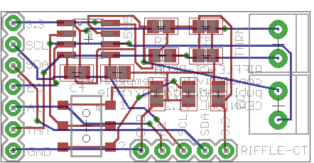
I recently submitted a through-hole version of this to OSHPark.com (the design is located in the same repository, above):
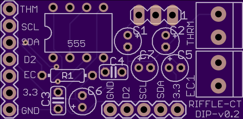
This version should be easy to use as a breakout board with other microcontrollers, while still being easy for folks to assemble themselves ...
Will report back when we get the new boards in!
6 Comments
This solder-yourself thing is a tough issue. The Riffle itself is always going to be surface mount, so you are going to have to manufacture them somehow and sell completed units. I assume you plan to have surface mount versions of all the sensor boards which will be manufactured and available for purchase. In addition you propose to have solder-yourself versions of the sensor boards so people can assemble their own. But won't it actually cost just about the same to sell a kit with through hole components as it will to sell a mass manufactured sensor board? Having two versions of each sensor board will complicate and slow your development process (every solder-yourself kit requires a comprehensive how-to-solder-this instruction guide) and maybe not save anybody much money.
It would be good to know how many potential customers would be willing to save a few dollars by soldering their own sensor board. These people will have to pay real money ($150?) to get a Riffle, so a few dollars savings on a sensor board might not attract many customers. I have been offering both solder-yourself kits and assembled and tested units of the SkyShield, and the ratio of sales is about 1:10 (i.e., I sold one kit). This surprised me considering the high geek quotient of the Public Lab community and the current importance of the "maker" mind-set. I think the truth is that there is still an incredibly tiny population of people who are prepared to solder a circuit board. And many of these solder-capable people are happy to pay a few bucks to avoid the time and risk of soldering.
Geeky people want gadgets that solve problems. A few of these are willing to do some soldering, but these are not your primary customers. Your target audience is people who need to know about their water. Almost none of these want anything to do with soldering.
Chris
Is this a question? Click here to post it to the Questions page.
Reply to this comment...
Log in to comment
I somewhat agree with @cfastie. I'm skeptical that there is value in a through-hole kit because there are only three components a DIYer would want to change, and they'd want to be able to fiddle with them in-process: the two resistors and a capacitor that define the 555's timer circuit.
I think we should think about development-specific use-cases: A through-hole board seems premature in a development scenario, as the resistors or capacitors may need to be changed during the sensor design process. Now, someone can work out their 555 circuit on protoboard, but that's not going to fit down a bottle neck.
So the DIY use case I see is wanting a board where the resistors and capacitors can be easily changed, but also a board that can reliably be attached to the data logger in field conditions. A through-hole kit doesn't meet this spec.
Either screw terminals or maybe even just 0.1" headers would let someone switch those three components out. Some balance between the cost of the connector and its reliability will have to be considered.
Reply to this comment...
Log in to comment
Thanks for all the good thoughts, wow!
Chris -- I think you're right -- your experience and our friend Rui's experience is that most folks don't want to solder something themselves.
Mathew -- definitely, a soldered, through-hole design like this isn't really the way to allow folks to swap out components -- e.g., changing the value of the capacitor in the circuit. If we want to allow for that, we should try to include screw terminals and the like, as you suggest.
And I agree: we should definitely also keep the surface mount versions; the majority of folks likely won't really want to tinker with the hardware, and are more interested in collecting data with the device. Distributing a through-hole DIY kit likely isn't really worth the trouble.
I think, though, that I will keep at least a few through-hole designs like this online, along with pictures of an assembled version, a list of parts (and places to buy them), and instructions for ordering the PCB from e.g. OSHPark. In my experience, and in that of most folks I've talked to about this (including Rui, Ben -- and I bet this is consonant with your trajectory, too, Chris), making the transition from 'user' to 'tinkerer' to 'circuit board designer' is much easier with through-hole components. Everyone I know personally who knows how to design a PCB began by designing through-hole boards. There's just something significantly more accessible about being able to design one's first PCB using the same components one uses on a breadboard.
So, for the majority -- surface mount, pre-assembled, and focus on simply collecting good data -- which is already hugely useful, and presents a world of challenges.
But in order to truly open up the design to contributions from the community, my notion of a process that might nicely facilitate this would be:
Going further: the next step for this design is to use a voltage divider to lower the voltage that enters the water, and amplify it with an op-amp when it emerges from the water. So, for a community that had some interest in technical development, I'd pose this as a problem, pointing them to appropriate components and online literature, and leading them through the process of making a simple change to a PCB in Eagle and ordering it from OSH Park.
This discussion brings up really interesting questions regarding the audience we're aiming for with such technologies, and points to how diverse these audiences might actually be. We do have the constraint of finite resources and time, so we can only e.g. imagine distributing a few versions of any particular kit. But we can, in parallel, provides links to useful alternative approaches that provide useful 'hooks' into the project for various levels of technical ability -- especially, hooks that will help grow a community of 'developers', not just 'users'. Perhaps this just means putting some time into making designs like this and documenting them sufficiently -- though, of course, as Chris points out (and knows well!) documentation also requires a significant amount of energy ...
Speaking of which, I'm fully in tl;dr territory here -- damn you, caffeine!
Reply to this comment...
Log in to comment
Don, that's a pretty good case for project R&D having an "in-between" stage where bigger production runs aren't ready to go but folks are making custom circuitry for field ready prototypes, and these boards will support that. Through-hole soldering equipment is readily available and cheap in a way surface mount probably never will be, given the number of components.
Reply to this comment...
Log in to comment
+1 "in-between stage" -- it could invite people into the process earlier without needing to yet 100% "nail it" on a final design, and hopefully folks using these prototype parts will help catch problems/improve the design before you go to a surface mount process. However, I don't know enough about the current state to say if you're past that stage or not, but I'm sure you do!
Reply to this comment...
Log in to comment
New data: I posted about the SkyShield at the KAP forum and got two orders in 24 hours, both for the solder-yourself kit! So disregard everything I said above (as if you didn't already). I'm taking the evening off because I don't have to solder two PCBs tonight.
Is this a question? Click here to post it to the Questions page.
Reply to this comment...
Log in to comment
Login to comment.