Just wanted to gather some useful materials around turbidity -- how it's usually assessed, and various approaches one might take to measuring it.
Background
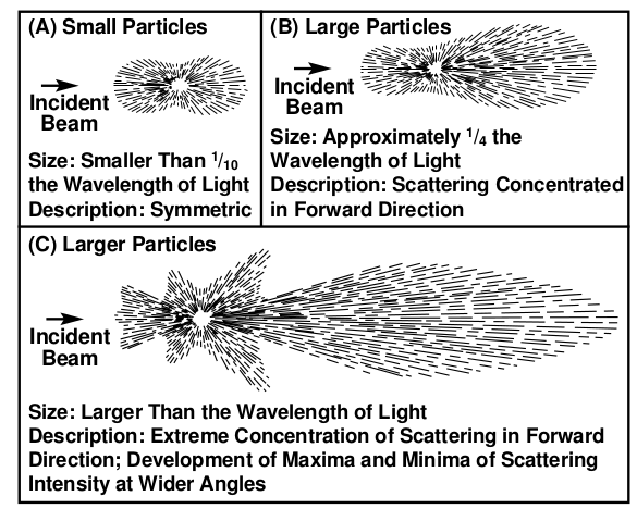
The gist (as far as I yet understand!) is: measuring the amount of suspended solids in water -- solids that haven't fully dissolved -- is a commonly used water quality parameter. In many contexts, having a lot of solids floating in the water -- stuff like silt, clay, algae, other organic matter -- is undesirable, so folks want some associated metric. For a rough measure, we can often simply look at a given sample of water -- water with a lot of solids floating in it will tend to look more opaque -- it'll look 'muddy'. But in order to really track changes over time, or compare different bodies of water, it's often nice to have a metric that is more precise than 'not very muddy' vs. 'pretty muddy'. [1] This motivates folks to define what they call 'turbidity': there are various specific definitions of turbidity, but in general they all involve an assessment of the amount of suspended solids that relies on shining light through the water, and then making optical measurements of what light emerges from the water sample. The idea is that solid particles will tend to scatter light in revealing ways, rather than allowing it to pass through in the manner it would without any suspended matter present in the water.
Sensor designs
We've found some good background readings that lead one through the various approaches to turibidity, and the associated designs / standards.
A sampling:
Basically, all the approaches involve shining a light into a sample and measuring what comes out. There are some details that matter regarding what wavelength(s) to shine into the sample -- some wavelengths penetrate water better, and the scattering pattern that results can also be wavelength and particle-size dependent.

The sensor approach and design will depend on the goal: what is one hoping to measure, to what standard? If one is simply looking for significant changes in turbidity from baseline, say, one might need to worry too much about things like the dependence of the signal on particle size or the color of the light source. But if one wants to compare measurements across sensors directly, or interact with regulation, one might want to follow one of the published standard methods.
For example, EPA Method 180.1 requires that a tungsten lamp be used as the light source; whereas the ISO 7027 standard specifies an 860 +/- 30 nm light source. This latter standard seems more easily accomplished in a field sensor, and has the advantage that the scattering is not affected by wavelength-dependencies.
Both the EPA Method 180.1 and the ISO 7027 involve a configuration in which the emitter and the detector are at right angles from one another (which is conisdered to better assess scattering from suspended particles):

Another method, the Great Lakes Instrument Method 2, further reduces error in the measurement by employing two sensor-emitter pairs, arranged in such a way that some of the typical measurement errors cancel, and the sensitivity of the instrument is enhanced:

Because of the complexity of this configuration, however, it seems better to focus on a single sensor-emitter pair, in line with the EPA / ISO standards. Typical sensor instruments implement this configuration in the tip of the probe (sometimes including detectors at angles other than 90 degrees (e.g., the 'back scatter' detector in the below figure) in order to attempt to do some error compensation:

First steps towards measurement
So, as a first pass, it seems like a good idea to focus on the simplest design that will provide useful data. In particular, I'm interested in building a 'turbidity alert' that detects changes from baseline; but it seems that this is accomplished by attempting to fulfill the ISO 7027 method, which is a fairly simple way of approaching the trigger system, anyway.
Chris Fastie's design
I had some very useful discussions with Chris Fastie about constructing a window system in an enclosure that would allow for such 90 degree orientations. He quickly sketched up some prototypes:


Chris' notes:
It looks like you have to measure light intensity at 90° from light direction. So you need a mirror. The design above has two features: 1) There is only one simple small window that has to be waterproofed. 2) The baffle keeps ambient light to a minimum but allows plenty of water to circulate in front of the window. Since you need to measure at 90°, you can just put a mirror on the baffle at 45°. Shoot the light straight out to it and measure it a cm from the mirror.
Pete Marchetto's design:
At a recent water quality sensor workshop in Port Jervis, NY, Pete Marchetto and Katy Hofmeister presented a turbidity sensor design that simply used an LED and an photocell pointing directly at one another:


The emitter and detector are hot glued to the outside of a plastic box, which is intended to be submersed in water. It was inspiring to see this simple design! In the design I'm pursuing, I'm thinking of trying to find a way to accomplish the 90 degree offset as in the above standards, and I might opt for a different light detector -- but Pete and Katy's design might be all one needs to accomplish a 'turbidity alert' device, and should probably be attempted in parallel.
Other designs
Along with these designs, there are several existing designs in the community for turbidimeters and the like:
Hackteria.org has collected several designs for a DIY turibidy meter: http://hackteria.org/wiki/index.php/DIY_turbidity_meters
Cornell has published a design for an open source turbidimeter -- particularlly nice is that they've worked to calibrate and compare their instrument against known standards and other commercial instruments, and present their methods and materials for doing so.
- 'Affordable Open-Source Turbidimeter' and: https://github.com/wash4all/open-turbidimeter-project
supplementary material: http://www.mdpi.com/1424-8220/14/4/7142/s1
cell concentration turbidimeter (open source ecology) http://opensourceecology.org/wiki/CellConcentrationTurbidimeter
Detectors
Collecting some promising detector options ...
A common light sensor is a very inexpensive photoresistor made of Cadmium-Sulfide:

The trouble with these sensors is that their response is both wavelength-dependent and strongly temperature dependent; also, the manufacturing process is typically very inconsistent. Such variations / dependencies can in principle be accounted for through a process of calibration and compensation: simply measure the response of the sensor to variations in wavelength and temperature, and use this response curve to adjust the sensor values. But in practice, it may be easier to simply find sensors that are produced with a less variable manufacturing process, and which e.g. have on-board temperature compensation. This doesn't avoid the necessity to calibrate and test the sensor, but can make the process much easier / less involved.
- An example of a more sophisticated sensor is the Adafruit TSL2591 High Dynamic Range Digital Light Sensor; tutorial

This sensor is sensitive to both visible and IR bands -- useful, 860 nm +/- 30 recommended in ISO 7027, and this is approaching near-infrared.
This chip uses a digital protocol (I2C) which is easy to implement on most microcontrollers.
Another possibility is an analog sensor, the GA1A12S202 Log-scale Analog Light Sensor. This means that the resolution of the measurement will depend on the resolution of the analog-to-digital converter used to measure it; the 10-bit resolution on Atmel 328 chips may or may not be sufficient. But it also has the simplicity of a simple voltage output, which can be tested easily and used in applications in which a full microcontroller with a digital protocol isn't ideal (perhaps a 555 timer based approach?
Speaking of simple protocols -- there also exist light level -> frequency converter chips, as per this device: http://www.ti.com/lit/ds/symlink/tsl235.pdf. This means that a light level could be output to a frequency.
Emitters
The other side of the process is the 'emitter' -- the light source. Here's a quick list of options found looking for LEDs in the range of 860 nm +/- 30 nm:
Surface mount chips at 850 nm: http://www.mouser.com/new/optoelectronics/infrared-data-communications/infrared-emitters-high-power/n-9frrm -- emit mostly out of top of chip
includes a lens: http://www.mouser.com/new/vishay/vishay-vsmy98545-emitting-diode/
also includes a lens: http://www.mouser.com/new/vishay/vishay-VSMB294002-VSMG285011/
another lens: http://www.mouser.com/ProductDetail/Vishay/VSMY2853G/?qs=%2fha2pyFadugK0phM2wfy67VmOV1pULyoxZhtFkoVwP8r9I2X0wJNtA%3d%3d
standard through-hole (might be good for right angle) : http://www.mouser.com/ProductDetail/Vishay/VSLY5850/?qs=%2fha2pyFadugHlaDgAnxVreaWM4F24NfyKTuez%2fhKXaXkF7mGSG1aBg%3d%3d
list of parts on digikey (search for 830 nm to 890 nm): http://www.digikey.com/product-search/en?pv40=17&pv40=874&pv40=873&pv40=574&pv40=615&pv40=19&pv40=44&pv40=181&pv40=8&pv40=877&pv40=643&pv40=586&pv40=63&FV=fff40008%2Cfff80028&mnonly=0&newproducts=0&ColumnSort=0&page=1&quantity=0&ptm=0&fid=0&pageSize=25
[1] Not always, though! Depending on the question one is interested in, or the audience, it may be enough to simply to e.g. take a photo of a river and show that it looks 'pretty muddy'. Mining operations and runoff from farmlands can turn normally-clear rivers muddy, and in some contexts this is enough to indicate a problem / trigger regulatory action. Also: a measurement of water 'transparency', which can be related to turbidity, using a simple Secchi disk device (https://en.wikipedia.org/wiki/Secchi_disk) has for several decades been used as a very effective way to track the evolution of turbidity in various water bodies.
4 Comments
Here's another design of an indestructible underwater housing. You should be able to build one with hardware store parts for under $15. No mirrors required, but you have to figure out how to waterproof three little windows.
Is this a question? Click here to post it to the Questions page.
Reply to this comment...
Log in to comment
OH. MY. GOSH. Amazing design (and video!!!). Can't wait to chat with you about this. Relevant electronics parts are being ordered presently.
Reply to this comment...
Log in to comment
Wow amazing mockup video. Any thoughts on slime buildup on sensor windows.? I don't know whether a heat-shrink tubing could be useful? http://www.mcmaster.com/#heat-shrink-tubing/=yokvmf
Is this a question? Click here to post it to the Questions page.
Reply to this comment...
Log in to comment
Neil,
Yes, the window slime will probably have to be removed every couple of weeks. Or maybe window transparency could be monitored with a separate optical sensor and a slime compensation factor could be derived. What might heat shrink tubing be useful for?
Chris
Is this a question? Click here to post it to the Questions page.
Reply to this comment...
Log in to comment
Login to comment.