380-930 nm resolution about 4 nm. Cost < 50GBP
Fully self contained (battery powered). With co...
Public Lab is an open community which collaboratively develops accessible, open source, Do-It-Yourself technologies for investigating local environmental health and justice issues.
It uses a TSL1402 diode array (I got mine from digikey) it has 256 pixels.
A holgraphic diffraction grating (1000 lines) plastic lenses x2 (3 cm focal length) (both form Greenweld). Microcontroller PIC16F1788 the light source is a torch bulb.
Here's a real spectrum which I stored on the SD card. It is of potassium permanganate. Because there is a very strong absorbance 500-580 nm and the sample is transparent elsewhere it is a tough spectrum to obtain experimentally due to random scattering off the diffraction grating.
There is some internal compensation for the scattering effect but due to limited processing power (the 16F1788 has an 8-bit processor) the correction is far from perfect.
It seems I can only upload JPG images so the spectrum has some JPG artifacts as well which were not present in the original GIF format.
The display uses SPI communication (it has an internal ILI9341 driver). The PIC16F1788 has a hardware SPI module. These type of TFT displays can be picked up for <£10 , but they refresh rather slowly due to the slow serial communication, but this is not a problem for this application.
The processor was programmed using GCBasic.
Apart from the programming it's fairly straightforward stuff. Bulb - slit - followed by a lens placed at 1 focal length should give a parallel beam then through the cuvette and onto the diffraction grating. Then a lens to focus the beam onto the diode array (approx 1 focal length between lens and diode array).
Getting the SD card to work was really difficult as there is little (and conflicting) information on the internet.
Yes I have no problem with that. It is however more involved than other projects I see on this site. It needs a lot of fine soldering (maybe a PCB could be fabricated to make this easier). It also requires a microprocessor and the knowledge and equipment to program it (I can make my software available). And of course some optical alignment is needed to get the light to hit the diode array (preferably in focus) and give the required wavelength range.
@david_uwi That's fine, some of our tools require more technical understanding; the wheestat also requires programming as well as soldering (to my understanding) but if it works, it works. Hopefully over time we as a community can simplify the build, or at the very least learn from it by knowing how its made!
Thank you so much for both posting this and joining our conversation!
is this something that a Raspberry or Arduino could be use to substitute for the processor - I ask due to the following that both processors have. also there "shields" that can be used to where only minimal amount of work is required to have a working circuit.
Hi @david_uw,
I am really impressed with your work :-) Very nice.
I would like to build your spectrometer.
Would you share your codes and assembling instructions ?
Did you already considered the possibility to connect your device through Bluetooth in order to use smartphone screen ?
This is the very first time I post here.. I hope I did it right.
Thank you.
Update:
The diode array has gone from obsolete to unobtainable in a matter of a few months.
I am testing an ILI1402 (made by ic Haus) which is supposed to be a direct replacement but without the small gap between the two 128 element dies, but it operates at 5V so I am evaluating various step-up converters. I am going to replace the colour display with a B/W reflective LCD as it will be much faster and will take much less current.
I am also looking into using a flash memory chip to store the data then transfer out with a USB connection as the SD card has given nothing but problems.
I am also tinkering with the optics to increase resolution and am probably going to add a UV LED along with incandescent bulb to improve the sensitivity below 400 nm.
Finally got something working using the ic-Haus LFL1402 diode array.
https://www.ichaus.de/iC-LFL1402
I normally use 3 V (2xAA bateries) so I had to use a step-up for the diode array (NCP1402 50T1).
I am using a bigger display (3" 400x240) it is also faster as it uses parallel communication It was obtained from DX.com (open smart).
Below is the test spectrum of didymium glass
and this is the menu screen
Notice the green asterix by the USB transfer indicating that the USB cable is attached. I have decided to use usb rather than SD cards this time (as SD cards turned out to be very difficult due to the number of different types). The spectrometer can store up to 24 spectra in flash which can be transfered by the usb link (using a FT201X I2C to USB chip).
The optics are a bit more involved as there is collimation onto the sample holder, followed by focusing onto a slit then further collimation onto the diffraction grating then re-focused onto the diode array. It gets much better throughput, but is very tricky to allign.
Public Lab is open for anyone and will always be free. By signing up you'll join a diverse group of community researchers and tap into a lot of grassroots expertise.

15 Comments
Very nice, but more detail is needed.
stef
Reply to this comment...
Log in to comment
It uses a TSL1402 diode array (I got mine from digikey) it has 256 pixels. A holgraphic diffraction grating (1000 lines) plastic lenses x2 (3 cm focal length) (both form Greenweld). Microcontroller PIC16F1788 the light source is a torch bulb.
Reply to this comment...
Log in to comment
Here's a real spectrum which I stored on the SD card. It is of potassium permanganate. Because there is a very strong absorbance 500-580 nm and the sample is transparent elsewhere it is a tough spectrum to obtain experimentally due to random scattering off the diffraction grating. There is some internal compensation for the scattering effect but due to limited processing power (the 16F1788 has an 8-bit processor) the correction is far from perfect. It seems I can only upload JPG images so the spectrum has some JPG artifacts as well which were not present in the original GIF format.
Reply to this comment...
Log in to comment
Hi, this looks really cool! Are you interested in posting build instructions so others can follow your steps?
I'm impressed at the cost -- what's driving the display?
Is this a question? Click here to post it to the Questions page.
Reply to this comment...
Log in to comment
The display uses SPI communication (it has an internal ILI9341 driver). The PIC16F1788 has a hardware SPI module. These type of TFT displays can be picked up for <£10 , but they refresh rather slowly due to the slow serial communication, but this is not a problem for this application. The processor was programmed using GCBasic. Apart from the programming it's fairly straightforward stuff. Bulb - slit - followed by a lens placed at 1 focal length should give a parallel beam then through the cuvette and onto the diffraction grating. Then a lens to focus the beam onto the diode array (approx 1 focal length between lens and diode array). Getting the SD card to work was really difficult as there is little (and conflicting) information on the internet.
Reply to this comment...
Log in to comment
Hi @david_uwi -- i'd like to help you format your notes into instructions that someone else could follow, would this be of interest?
Is this a question? Click here to post it to the Questions page.
Reply to this comment...
Log in to comment
Yes I have no problem with that. It is however more involved than other projects I see on this site. It needs a lot of fine soldering (maybe a PCB could be fabricated to make this easier). It also requires a microprocessor and the knowledge and equipment to program it (I can make my software available). And of course some optical alignment is needed to get the light to hit the diode array (preferably in focus) and give the required wavelength range.
Reply to this comment...
Log in to comment
@david_uwi That's fine, some of our tools require more technical understanding; the wheestat also requires programming as well as soldering (to my understanding) but if it works, it works. Hopefully over time we as a community can simplify the build, or at the very least learn from it by knowing how its made!
Thank you so much for both posting this and joining our conversation!
Reply to this comment...
Log in to comment
is this something that a Raspberry or Arduino could be use to substitute for the processor - I ask due to the following that both processors have. also there "shields" that can be used to where only minimal amount of work is required to have a working circuit.
would you have a schematic that you could post?
Is this a question? Click here to post it to the Questions page.
Reply to this comment...
Log in to comment
Hi @david_uw, I am really impressed with your work :-) Very nice. I would like to build your spectrometer. Would you share your codes and assembling instructions ? Did you already considered the possibility to connect your device through Bluetooth in order to use smartphone screen ? This is the very first time I post here.. I hope I did it right. Thank you.
Is this a question? Click here to post it to the Questions page.
Reply to this comment...
Log in to comment
Update: The diode array has gone from obsolete to unobtainable in a matter of a few months. I am testing an ILI1402 (made by ic Haus) which is supposed to be a direct replacement but without the small gap between the two 128 element dies, but it operates at 5V so I am evaluating various step-up converters. I am going to replace the colour display with a B/W reflective LCD as it will be much faster and will take much less current. I am also looking into using a flash memory chip to store the data then transfer out with a USB connection as the SD card has given nothing but problems. I am also tinkering with the optics to increase resolution and am probably going to add a UV LED along with incandescent bulb to improve the sensitivity below 400 nm.
Reply to this comment...
Log in to comment
Finally got something working using the ic-Haus LFL1402 diode array. https://www.ichaus.de/iC-LFL1402 I normally use 3 V (2xAA bateries) so I had to use a step-up for the diode array (NCP1402 50T1). I am using a bigger display (3" 400x240) it is also faster as it uses parallel communication It was obtained from DX.com (open smart). Below is the test spectrum of didymium glass
Notice the green asterix by the USB transfer indicating that the USB cable is attached. I have decided to use usb rather than SD cards this time (as SD cards turned out to be very difficult due to the number of different types). The spectrometer can store up to 24 spectra in flash which can be transfered by the usb link (using a FT201X I2C to USB chip). The optics are a bit more involved as there is collimation onto the sample holder, followed by focusing onto a slit then further collimation onto the diffraction grating then re-focused onto the diode array. It gets much better throughput, but is very tricky to allign.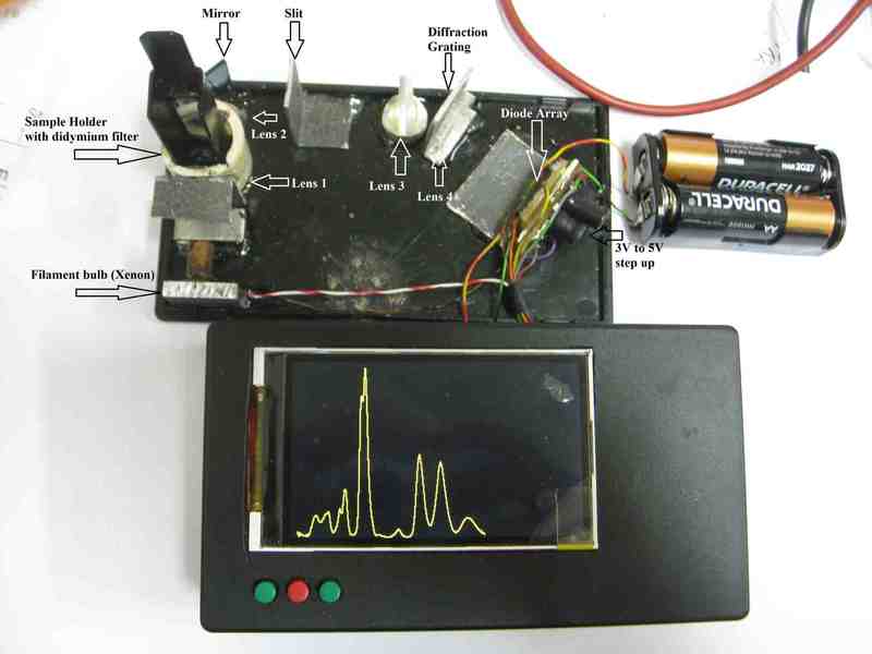
Reply to this comment...
Log in to comment
SPEC2018-2-.bmp
This is the circuit diagram
Reply to this comment...
Log in to comment
Thank you for example of the device circuit diagram. It based on microprocessor. Without example of firmware the circuit diagram meant almost nothing.
spectrometer16f.gcb.txt
Reply to this comment...
Log in to comment
Login to comment.