This project proves the construction, without testing of spectra, that a desktop spectrometer can be built with no wooden block and with no velcro.
I was able to construct a DSK using no additional parts, and without using the wooden block, wooden platform, or velcro. This reduces the weight of the DSK by 2.1 ounces, and allows the item to be mailed in a large, flat envelope, which is subjected to somewhat lower domestic shipping costs, and dramatically lower international shipping costs.

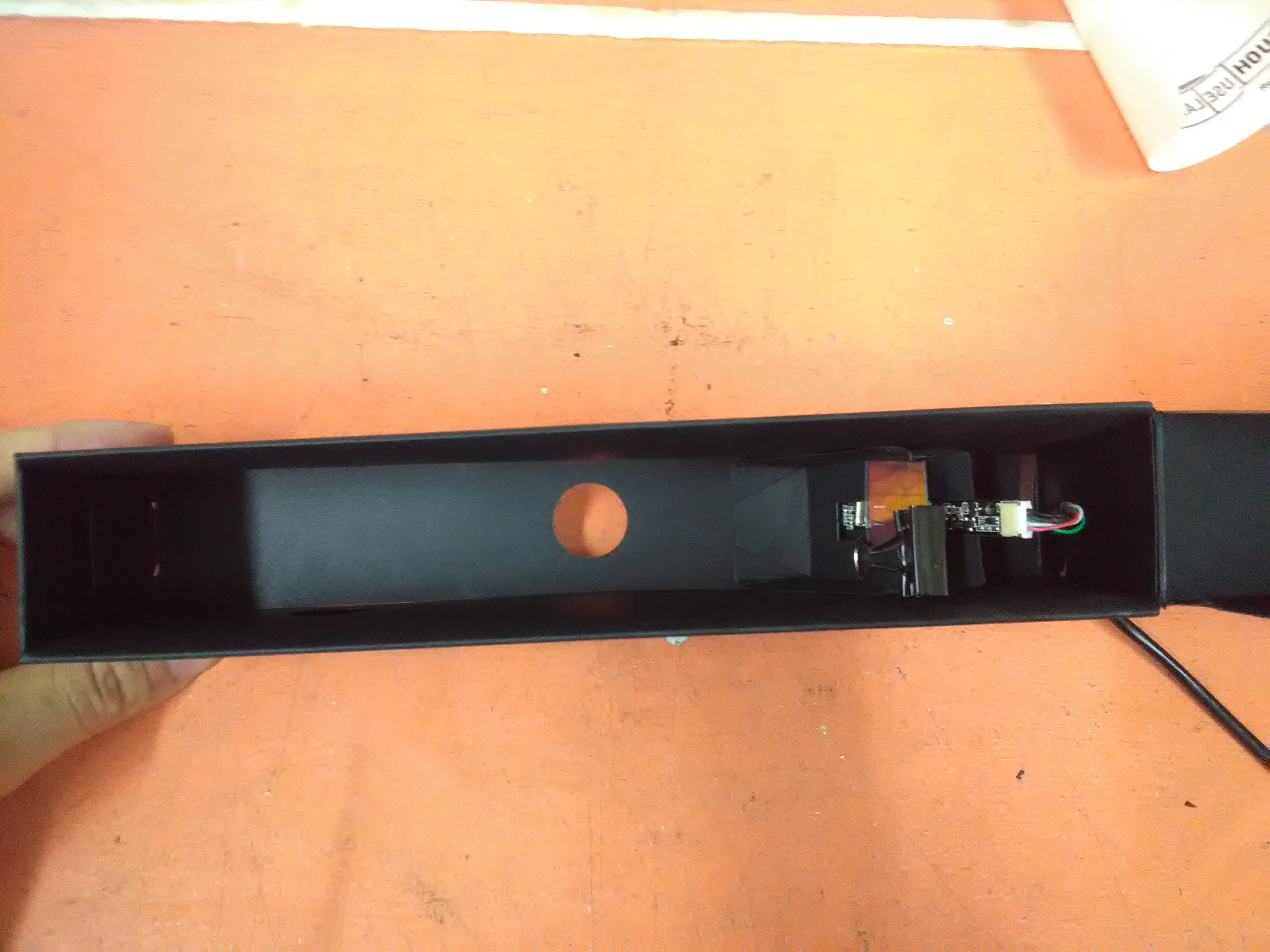
Above you see kind of the final product. Next you can see an unfortunately grainy image of the interior, a bit hastily constructed. Of course, this has much room for improvement.

The build is made possible by the piece shown below, which comes shipped with every Desktop Spec Kit

The next images show how this piece is folded


So you can see this piece folds into kind of a triangle, where a piece of double sided taped is placed across the two outer pieces, as shown below.

And folding the middle piece up and pressing it against the sticky tape.

The next image proves that this folds into a 45 degree angle, which is the angle of this item is the same angle that the DSK is designed for, and the same angle of the wood block.

To complete construction, add double sided to the bottom like so

In order to prove it can sustain a load without moving, I rested a box cutter against it, which is much heavier than the webcam used in the DSK.

Questions and next steps
In order to affirm the feasability of this, the DSK must be tested to see if the DSK can read spectra.
Why I'm interested
If this modification works with some adequacy, the selling price of the DSK can be lowered, and international purchasers of the DSK can be saved from sometimes very expensive customs charges.
Assembly Instructions (Under Construction)
Your spectrometer is composed of three functional elements:
- a collimation slit that works as a lens, only allowing parallel light rays through its apeture.
- a diffraction grating that deflects light more the lower the light's wavelength, creating a rainbow diffraction pattern.
- a camera to capture the diffraction pattern, focused on the collimation slit.
Make a diffraction grating from a DVD
Do not touch the surface of the DVD, always hold it by the edges, fingerprints will blur this important optical component.
We are going to turn a DVD-R into a diffraction grating, a device for separating light by frequency. An ideal diffraction grating would create a straight rainbow. A DVD produces a curved rainbow, but its rigidity and consistency make it a very good grating, and the tiny webcam lens curves the spectrum anyways. Aligning your diffraction grating will take some tweaking. We’ve given you extra material to help.

We have three steps, cutting a quarter of the DVD out, peeling off the reflective aluminum side, and trimming to a small piece.

OPTIONAL: Wash the purple ink off of the DVD fragment for greater light transmission, as described in this note.
Peel apart a quarter of the DVD
Cut out a quarter of the DVD with scissors. It may take more than one try to get a good diffraction grating, so save the rest too.
Use a knife or a fingernail to dig under the corner of the DVD quarter and peel the two layers apart.


You will get two layers. We are trying to get a transparent purple piece without aluminum stuck to it. If you can’t find a good piece you may want to try another quarter DVD. You only need a 2cm (.75”) square cut from the outer edge. Trim down to a small square with roughly 2cm of the DVD’s outer edge.

Trim down to a small square with roughly 2cm of the DVD's outer edge.

Prepare the Webcam Angle
In order to prepare the webcam angle, you must use this piece of paper from your Desktop Spectrometry Kit, which Looks like this

This piece folds into a triangular piece. You want to first fold it longitudinally at each crease, and then fold the shorter creases inwards until they connect.
The first fold looks somewhat like this

And after folding both sides longitudinally, folding along the short creases will bring it to look like this

From here, crease the bottom portion. After it is creased, flatten it and apply sticky tape so that the bottom portion will close upon the other two pieces (which are now touching, folded inward). While difficult to describe with words, this is fairly easily represented in pictures; see below:

Pinch them closed firmly and hold to ensure the pieces stick together well. Make sure that no corners or edges are left unadhered.

Assemble the diffraction grating angle
You will need:

Overview:

When taping the three flaps together, make sure the bottom flaps are lined up. Put Two sided tape on the bottom.


Put the outer edge of the dvd at the mid-point of the hole, and then remove the handles from the binder clip.

Now, put a strip of double-sided tape on the back side of the camera:

Of course, remove the red exterior of the double sided tape to ensure that it sticks on both sides.

Now, place the camera on the paper angle with the white cable port on TOP. Place the camera slightly above the bottom of the block. 1/8 to 1/4 of an inch should do. This is because in the traditional spectrometer, a wooden platform is placed beneath the webcam, lifting the camera slightly. Without the wooden platform, we will lift the camera as well as lower the acetate slit later on, in order to try to get our light to line up properly.

Align the diffraction grating
You will need:

While these items are identical to the items used in the traditional build of the Desktop Spectrometer, it is important to note that the acetate slit is not aligned with the two white lines on the edges, but is instead lower (note that the two white lines are not in the exact middle of the slit card, but instead are shifted more to one side. You want your acetate slit shifted down into the larger portion of the slit card, the one that has more area below the two white lines).
Your slit card should look something like this once sticky tape is applied to hold it the acetate:

Assemble the box
Watch this step-by step video:
For the purposes of this instructional I've highlighted the edges of the box in white and used an unprinted box. Your box will have a printed and unprinted sides, and no white edges.
Place the box with the printing facing down. Pre-crease all the creases towards you. and crease the box top as well.


Fold the left side "T" shape over to the right, and insert the tab from the leftmost edge into the slot at the base of the "T", as shown here:

Lay the separate box top piece on top so that its tabs line up with the slots in the box bottom’s right side. Make sure the small rectangular holes on the top and bottom of the box line up. We will put the webcam cable through that hole later. Insert the tabs together. The box top will not lay flat-- don't worry. this is because there is extra space for the two sheets to fold together.


Now open the box back up and fold left and right side flaps to the middle to form the inner walls. They will hook together.


Fold the outer walls up and over the inner walls. Use the two circular holes in the outer walls to position the inner walls while folding the outer wall over.


Flip the box upside down and make sure the tabs have all popped out of the bottom of the box. Walk your fingers along the inside of the box and make sure all the tabs are popped out of the bottom.

Place your components within the box
In order to place your components within the box properly, you will need a tape measure or a ruler, which is unfortunately not included in the kit currently. You could also eyeball it, but of course it is best to use some kind of actual measurement.
The base of your angle needs to be 1.75" forward from the back of your box. In order to achieve this, you could measure 1.75" forward if you can; but you might find that difficult. A workaround is to measure a 1.75" length of the extra cardstock included in the kit, trim it, and place it within the box to mark 1.75" with a pencil.


After trimming a 1.75" width of cardstock, you can place a strip of it into the box like I have done with a white piece of paper (so that it could show up in a photograph)

You want to mark the distance, that mark is where the edge of the angle that the webcam sits atop will go.
Place double sided tape along the bottom of the angle that holds the webcam

Then, place it into the box and firmly press it in, at the line you previously marked.

Next, it is time to move back to the diffraction grating. You'll want to place double sided tape along the bottom of that piece much akin to how you did with the webcam angle.

You want to place the diffraction grating snugly right near the webcam, like so

Thread your USB cable through the back

And plug it into the webcam.

Close up the box, you're done with construction!
Head over to Now connect to your spectrometer using the web-based software at Spectralworkbench.org
You might want to find some activities to do with your spectrometer. Those can be found here:
11 Comments
Hi, Abdul - this looks great; do you imagine we could offer the spec both with/without the wood piece? I know some people have wanted more rigidity, like in this prototype. We could maybe separate out the basic kit from the various ways of getting more rigidity.
Also, i think it'd be possible to include another piece of stiff paper that could be folded into a more rigid block for the webcam, without the overhang. One issue is when the cable is tugged, it can move the webcam if it's not super well secured. Just a thought!
Is this a question? Click here to post it to the Questions page.
Reply to this comment...
Log in to comment
And just checking, maybe this could be marked as in-progress? Could we try a tag
status:in-progressand could you add it to the new grid: https://publiclab.org/wiki/spectrometry#Hardware+ModsIs this a question? Click here to post it to the Questions page.
Reply to this comment...
Log in to comment
Hey Jeff,
Yeah, feel free to add any tag, I'm not as familiar with the formatting capabilities or standards typically used on the site.
Regarding rigidity, unless we get to a state where storage space is limited, there is not currently any issue with continuing to store velcro and wood.
Reply to this comment...
Log in to comment
Well, we're still working the tagging out in this thread: https://groups.google.com/d/msg/plots-infrared/8IYLt3rdw2w/k4EJPRx4DAAJ, but if you add it to the grid, we'll go back through once we've figured it out and give it the appropriate tags. Thanks!
Reply to this comment...
Log in to comment
Hello @abdul, ok, I thoroughly read through your post and your note also, about processing the DVD piece, I want to just start their for a minute, the "purplish" layer that is left is very inconsequential as it relates to any spectral data collecting. First here is a chart that breaks down the effect that many chemicals and solvents have on various types of plastics:
On the top left of the chart you will see "PC," this is the DVD (polycarbonate) and you will also notice that it is susceptible to damage from various solvents and chemicals. The entire DVD piece can be processed at once, I have made hundreds of them over the months, so I know a little something about this, I process half of the DVD at a time by carefully scoring (using a n Exacto knife or you can use a new razor blade,) to cut around and through the bottom silver strip and top silver strip on the DVD piece.
Take strips of good Duct Tape and firmly adhere it to the half you just scored, and I promise you that, 99% of that purple layer will pull right off along with the aluminum, the rest just don't worry about it, look at the DVD and find the best section of it and cut it out from the bottom up, so you can keep it's curved shape. That's it!
Ok, all that said, your design is clever, and I understand the reasoning behind it, I particularly was impressed with the use of the protractor to verify the angle of the camera mount. I do have a suggesting though, on the instructions for the DVD piece, I would just keep in mind the chart I provided above, as an aside if you want to keep the part about the optional washing of the DVD piece.
Over all though, without actually testing , it should work, although I will say that its performance will be severely limited in the context of a precision analytical tool, but will do just fine as an excellent learning tool!
I say this, only because alignment and stability are so very critical, I would like to test it out for you if you would like, even in it's present incarnation, I think it will work.
Please let me know?
Best regards,
David H Haffner Sr.
Is this a question? Click here to post it to the Questions page.
Reply to this comment...
Log in to comment
Hi, Abdul - I marked this as an activity for the DSSK; could you try adding detail about how long it takes to do, and how difficult it is? Thanks!
Is this a question? Click here to post it to the Questions page.
Reply to this comment...
Log in to comment
Yes I'll add details
Reply to this comment...
Log in to comment
Well, I couldn't quite see how to edit the activity grid, but I'd put the stats as ready for testing, the difficult as very easy (assuming a scale of 1-10 is where 1 is the difficulty of building a 3.0 without any changes, that's how hard this is) and I'd say it takes about 35-40 minutes.
Reply to this comment...
Log in to comment
So just above the tag box, there's a little "quiz" to add details -- fill that out and it'll auto-tag your post appropriately! You can enter custom times/values yourself manually as tags too, once you see the format.
Reply to this comment...
Log in to comment
I think the main challenges are:
Both of these would need to be tested -- preferably in some standard way we could outline here, stepwise, so that others can try them out. Thanks!!
Reply to this comment...
Log in to comment
@stoft has proposed a set of tests and thresholds for different rigidity"standards" of sorts, here: https://publiclab.org/notes/stoft/09-15-2016/what-mechanical-specs-can-and-should-plab-spectrometers-meet
Reply to this comment...
Log in to comment
Login to comment.