Working with microcontroller development boards like the Arduino or the TI LaunchPad provides an easy introduction to writing code and using a microcontroller to read inputs or to output stuff from a computer. While this provides the flexipbility and freedom to do a whole lot of cool stuff, there are a lot of things the evaluation boards by themselves cannot do and using shields can expand your capabilities to do things like reading sensors, and run motors or CNC mills. Designing and building your own shield can further extend what you can do and also provide a fun challenge. At some point, however, you might want to build a stand alone device that does not require the Arduino or LaunchPad. That is, a board of your own that incorporates the microcontroller chip, power supply, oscillators, and other peripheral hardware necessary to do what you envision. There are a lot of good resources available for most Arduino applications and this is no different. Sparkfun has a tutorial for programming Atmel microcontrollers (like in most Arduinos) here. In this research note, we describe some of our work to build and program a stand-alone board that incorporates the TI TM4c123 microcontroller. The board described in this note was designed as a part of our update to the WheeTrometer spectrometer (as described here). The LaunchPad development boards can be programmed using Energia, which is an IDE written by the same people that wrote the Arduino IDE. The two are very similar in look and functionality. In addition to Energia, TI has an IDE called Code Composer Studio that can be used to write code for and program the LaunchPads.
Board design notes.
We designed our board in Cadsoft Eagle freeware using information available for the Tiva C LaunchPad development board as our guide. The parts and the necessary connectivity can be found in the Tiva LaunchPad users guide, available here. The Bill of Materials is on pages 17 and 18 and the schematic is provided on pages 20-23.
Design Note 1: Since you will need to program your board through the JTAG pins (TCK, TMS, TDI, TDO and RESET). Make sure you have these pins broken out or otherwise accessible. Pin numbers are 52, 51, 50, 49, and 38.
Design Note 2: One thing that gave us a bit of trouble was the VBAT pin. While we originally left it disconnected (since we were not using battery power), we were never able to program the chip on boards with the VBAT pin disconnected. It turns out that this pin senses when your battery is running low and we suspect that leaving this pin disconnected may prevent the microcontroller from exiting a sleep mode. After connecting this pin to the +3.3 volt circuit, we were able to load programs onto the board.
Design Note 3: Since we make prototype boards by hand, one at a time, the smallest components we use are 603 packages. The schematic for the LaunchPad development board shows a bunch of small capacitors that, at 603 scale, take up a fair bit of pcb real estate. It occurred to me recently that a good bit of board space could be saved by putting these caps on the bottom surface of the board. While this would not work in a production mode where you are assembling by reflow, the method should be amenable to assembly with soldering iron and tweezers. I have not tried this yet but we plan to in the near future.
Building Notes: The TM4C123 microcontroller has 64 pins distributed along all four sides of a ~1 cm square piece of plastic on 0.5 mm centers. The tight spacing of pins and the square distribution make it a challenge to solder. Actually, it is not the soldering that is a problem, it is the placement of the IC that is a challenge. What I try to do is tack the bugger down by one pin and check the alignment under a microscope before taking down the opposing pin (pin 1 is opposed by pin 33). With a square IC like this, it is much more difficult to achieve proper alignment than with an IC with two rows of opposing pins (like a SOIC chip). With a SOIC chip, if you get it aligned left to right, you are done. With the square chip, if it is aligned left to right but offset in the up/down direction, the pins on the left and right sides will not be attached correctly and the chip is not going to work. If the chip is not properly aligned, do not tack down the second pin. Instead, melt the solder and re-align until you get it right.
Once you have the chip aligned, it is pretty straight forward to solder with a soldering iron. It just requires patience, flux and a bunch of solder wick. I recommend using a minimal amount of solder and then removing most of it with solder wick. You can make your own solder wick just by stripping stranded copper wire and poking it into flux.
Programming Notes:
Each launchpad development board has two microcontroller ICs. The one you want to program is called the "Device", the other is the In Circuit Debug Interface (ICDI). The "Device" microcontroller is programmed by input from the ICDI by JTAG. The JTAG pins on the development board are broken out with wirepads on 0.1" centers. You need to connect the JTAG pins on your custom board to the JTAG pins on the development board. In addition to the five pins listed above, you need to power your board and prevent cross-talk from the development board Device microcontroller. Removing the power jumper on the development board will prevent cross-talk and provide access to a +3.3 volt power source on the left hand pin. Use the +3.3 volt pin and any ground connection on the development board to power your custom board.
We had some early programming difficulties with our custom microcontroller board that we thought might be hardware related, so we worked to transfer a program from one LaunchPad to a second LaunchPad. To transfer a program from one LP to another, set the things up with the JTAG pins from the first LP wired to those from the second. Connect the two grounds and power the second from your +3.3 volt source on the first. This is shown in the figure below. Once this was all set up, we were able to connect to the first LP via the Energia IDE and successfully programed the second with the 'blink' program by selecting download.
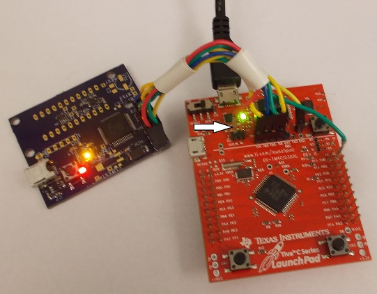
Using what we learned from the above experiment, we were able to program our custom circuit board. Our method for powering the board is shown in the main figure for this research note. While it does not show up well, there is a red wire leading from the 3.3 volt pin on the launchpad board to the power pin on the new board. The connection of this wire to the launchpad is indicated by a white arrow. The ground wire is the green wire in this figure. To test our ability to program in this way, we used the Energia IDE to transfer a simple blink program to the custom board. Our ability to control the rgb led using this method indicated that it did work.

So what comes next? Well, next we have to get the WheeTrometer firmware all debugged and load it on the custom board. then we have to build the optical hardware and get the CCD secured on that. Then we write the user interface and we are all done. So maybe we are not all that close to being finished with this project but we are making progress.
3 Comments
With your vbat pin, did you connect it directly to the +3.3v or go thru a pull up resister? What value resister did you use?
Very interesting project. I missed the schematics, maybe because I didn't read well. Can you point them out? Thanks.
Is this a question? Click here to post it to the Questions page.
Reply to this comment...
Log in to comment
Hi Ag8n, Thanks for the comment. I am glad you are interested. We just connected the VBAT pin to the +3.3 volt bus.
You did not miss any description of the circuit. I just dont like to put them out until I know that they work and have code that works with them. I think we are pretty close, but have not had time for this particular project. The circuit board is similar to the one described here: https://publiclab.org/notes/JSummers/08-16-2018/wheetrometer-spectrometer-update-part-2. If you want more detail send me an email at summers at wcu dot edu and I will provide eagle files, etc.
Best, Jack
Reply to this comment...
Log in to comment
Can you please post the full connection as I'm trying to do the same but it's not working for me
Reply to this comment...
Log in to comment
Login to comment.