Goal:
This note is the second to look at updating the Wheetrometer spectrometer. The original Wheetrometer design was described by Ben Hickman in this post and was updated for a 3D printed version here. In June 2018, I posted a note on updating the spectrometer that can be found here. Since that last post, we have been working on microcontroller firmware for the updated instrument. The firmware needs to enable the microcontroller to do the following: 1) it must communicate with a host computer. 2) It must accept instructions from the host computer, including parameters like integration time. 3) The microcontroller must output coordinated signals to three pins on the charge coupled device (the light sensor, also called CCD or photodiode array). 4) The microcontroller must measure the output voltage from each cell of the CCD, convert the analog voltage to a digital value and 5) it must transmit that data back to the host computer.
What we have done:
We have been working with Code Composer Studio to write C based code. While this is not a finished product, we have made some good progress and have posted the current code on our github page. While I generally prefer to have something more finished before putting it out there, school is about to start and progress on this project is going to slow down significantly.
Where we are:
Referring to the numbered points in the Goals section above, we have made the best progress on points 2 through 4: we are able to use information from the host computer to adjust delay times (point 2), output the required signals to the CCD (point 3) and measure the output voltages. In the past month or so, we have focused most of our work on points 1 and 5, communication with the host computer. We are working on code that will allow the instrument to communicate through the 'device' usb port, thereby bypassing the need for the In Circuit Debug Interface that the LaunchPad development board employs for programming and debugging. We have posted a short video that shows how the current code communicates over the device usb port.
What still needs to be done:
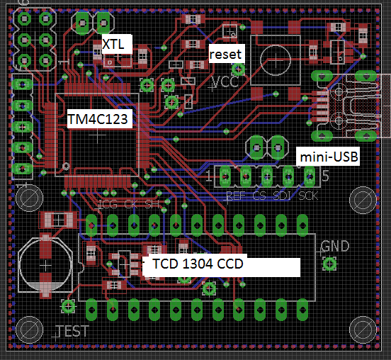
There still needs to be some debugging on the communications code and we have not started work on outputting the data from the microcontroller to the host computer over the device usb. We do have that working over the debug interface, but ... Once we have that, we will need to update the user interface on the host computer and make sure that everything plays nice with everything else. We also need to further develop the electronic hardware (the circuit board in the photo above is on order) and make sure we are able to program the microcontroller without the debug interface. There is also the optical bench aspect of this, so there is still a lot to do..
0 Comments
Login to comment.