The problem: Overexposure.
Often - especially when taking sunlight spectra - I have the problem of overexposure. Either the software clips single colour channels or the webcam's AGC regulates everything down no matter what. This results in compromised spectral data.
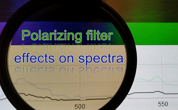
A possible solution: A polarizing filter.
Sun light is a sum of light rays of lots of different polarisation angles. The idea is to block/filter out a part of the whole bunch in order to "dim" the sun and lower the intensities without changing the peaks' wavelengths.
Let's test it:
First I try a crude setup with a Phillips energy saver LED table lamp, my PLab spectrometer 3.0 and a single Walimex Pro circular polarizing filter directly in front of the slit.
First results:
On the spectrum capture page you see it immediately that the intensity curves go down. Have a look at the "waterfall picture":

But will the curves' peaks still be found at the same wavelengths? First the "average" curve with and without filter. Although the overall shape of the curve comes pretty close there are changes in peak wavelengths. Here is the graph:
 (the red line is the curve with filter, the blue line without)
The biggest difference you can see in the red range at about 614 nm, but there are other differences as well. For instance that little "hill" at around 494 nm is missing in the filtered curve. And the left peak of the filtered curve is much lower than the right peak of the filtered curve, whereas in the unfiltered curve they are almost same height. The filter "steals" more light in the blue area here. (Perhaps that might change depending on the rotation angle of the filter itself. Put in front of a DSLR camera you can turn it and get cooler or warmer colours...)
That means there are substancial changes between the filtered and unfiltered spectral peaks.
It seems that a polarizing filter is not working too well as "light dimmer" in spectrometry.
In the next step I will compare the colour channels to see which colour curve suffers most at this filter's angle. After that I might try a different angle of the filter itself, too.
The red curves:

In the darker (filtered) curve almost all red in the 464 nm area is gone. The "hill" on the right hand side looks like the "little brother" of the lighter (unfiltered) "hill".
The green curves:

Again, most of the green is missing on the left side "hill" while on the right side we even have pretty different shapes in the darker (filtered) and lighter (unfiltered) green curve.
The blue curves:

Here we have the biggest effect on the spectrum. While the left part of the blue curve is wiped out just like the green left part the polfilter "flattened a whole mountain" on the right hand side. The double peak becomes a single peak.
Conclusion:
As I said before: a polfilter is not a solution for overexposure problems as it changes the peaks of a spectrum too much, not only in intensity but in wavelength' terms, too. The angle of the polfilter itself was so that it wiped away more light on the blue side of the spectrum thus letting things appear warmer (more red). A different angle could change this into a cooler (bluer) appearance wiping away more of the right hand side of the spectrum.
If you want to check data - here is the Excel format file:
1 Comments
My guess is that the wavelength transmission curve of the glass (depending on type) softly "rolls off" for shorter wavelengths -- i.e. the glass is probably not a 'flat' transmission response. There is probably a low pass filtering effect from the polarization coating on the glass. Ideally, what you'd need is a neutral density filter which has the transmission curve specified to at least cover the spectrometers 400nm end. A cheap-and-pretty-good attenuator can be made by printing diffuse 'neutral-grey-density' patterns on sheet inkjet-printable film. They are not terribly flat but work for relative measurements.
Reply to this comment...
Log in to comment
Login to comment.