Abstract:
Although current open-source spectrometers analyze the entire visible spectrum at a relatively low resolution. This new, low-cost spectrometer analyzes the spectrum of a laser diode at the sub-nanometer scale. The lens-grating-lens geometry distinguishes spectral features, such as the harmonic modes of a 650nm red laser diode, at wavelengths 0.16nm apart: giving it a resolving power ratio of around 4070. It makes use of a RaspberryPi, PiCamera, and readily available optical and electrical components costing around $100 USD. The captured spectra is uploaded to spectralworkbench.org in order to determine the wavelengths of the modes. The modularity of this system can adapted to a variety of optical and optoelectronic experiments for insights into optics, spectroscopy, and optoelectronics at a low cost of entry.
Introduction:

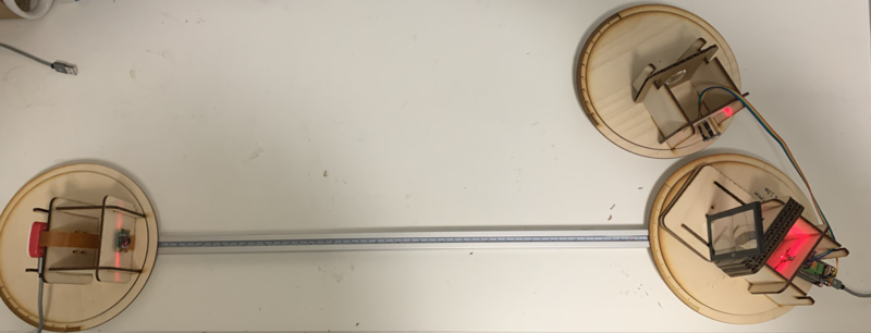
This is a continuation of a post I made in March. The design was updated and more things have code. Some theory is handwaved in this note in order to be more clear about the experiment itself. This spectrometer was born out of a necessity for a series of labs for a modern optics course. It is supposed to be a transforming optics bench that can turn into a variety of experiments. OpticCube (the name of the device) is an optical test bench that can be built at any makerspace or fab lab. Advances in optoelectronics dramatically reduce the cost of components like lenses, gratings, and CCDs bringing the total cost to around $100 USD with many of the parts sourced from mainstream online retailers. As seen in Figure 1 Most of the optical components and electronics are mounted to laser cut bulkheads mounted onto goniometers which themselves are bolted onto 2020 extruded rail. The bulkheads (on Github here) hold lasers, lenses, gratings, and detectors (PiCamera CCD); a new component can easily be integrated by cutting a new pattern into the bulkheads. This spectrometer uses a configuration called lens-grating-lens which means the grating sits between a collimating lens and a focusing lens.
The secret diode laser companies don’t want you to know.
Laser diodes come in a variety of different tolerances. Theoretically, diode lasers are monochromatic sources (single frequency and wavelength), however in practice there is some degree of tolerance to this monochromatic-ness called linewidth. The difference between a 50 cent diode and a 50 dollar diode (at 650nm nominal wavelength) comes down to the linewidth – the expensive diode emits a much narrower band of ‘pure’ red light. Fortunately, the cheaper laser’s linewidth is wide enough that other harmonic modes emitted inside the laser cavity (similar to a guitar string) are detected by the OpticCube.
LGL Spectrometer Geometry

The LGL configuration was chosen because the the optical path can remain in line which minimizes the degrees of freedom required to adjust the experiments. It gives easy access to both the source and detector and demonstrates a clear optical path without a labyrinth of mirrors at the cost of space. This is all possible through a holographic transmission grating card. First, any lens on the laser is removed to reveal the diode. As seen in Figure 3 the point-source light from the laser diode's cavity is collimated by the first lens with a diameter of 29mm. This 29mm column illuminates 29000 lines in the grating which means more point sources to interfere with each other. By focusing the interference pattern generated by the grating onto a detector relatively far away, the diffraction pattern appears as wide enough to cover the PiCamera's sensor. By swapping this second lens, the user can change the bandwidth detected. Without the grating, these optics essentially magnify the laser diode and with the grating it diffracts the harmonic modes that appear as the same image of the laser but from a different wavelength emitted by the laser at a different position on the detector. While lenses have the bad reputation of having chromatic aberration, this doesn't matter much because a) the primary lens only serves to focus the light coming from the laser (or slit) and b) lasers are relatively monochromatic.
Running the experiment

The experiment is broken into two parts: the spectrometer (Figure 4) containing the test source and the LGL geometry, and a Raspberry Pi Camera without the lens as a CCD detector. The grating is sandwiched in the mass of cardboard and wood which also houses the lens. A perpendicular angle between the column of light and the grating might not be the best geometry, however it does well in keeping the lens and grating rigid. The secondary lens, a cheater lens for a welding mask having a long focal length is propped on the side facing the detector. This lens can have a focal length of 40cm to 130cm depending on the lens used, but in this case at 1.0 diopters the secondary focal length is 100cm. This distance is important for determining the angle of each peak.
Imaging

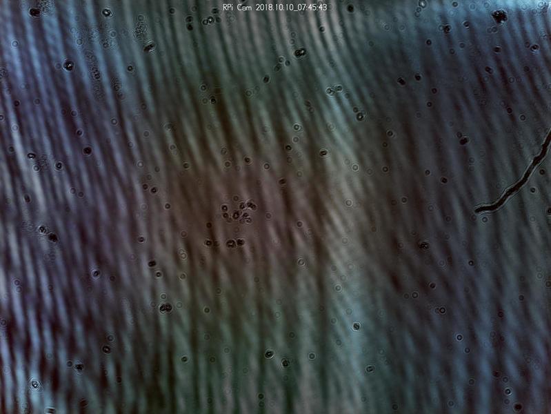
The raw output of the PiCamera in Figure 5 is a series of vertical bands distorted by dust (the dots) and manufacturing impressions from one of the lenses (diagonal lines close together). The Raspberry Pi runs the PublicLab stock image, with the camera settings tweaked to allow for the full resolution of the image for a Pi Camera V2. The Pi Camera has a pixel pitch of 1.12 um; each pixel of the full resolution image corresponds to a measurable point on a grid. The software black boxes that compress the image into JPEG take the value read from pixels and averages the colors causing some error in the results. Spectralworkbench can condition this spectrum into usable data as seen in Figure 6.

Without calibration spectralworkbench outputs a map of the pixel intensity versus pixel number, a feature that proves particularly useful for this application.After sampling the image, spectralworkbench outputs the intensity values. If the image is clear, spectral workbench will show a graph with periodic peaks corresponding to harmonic modes of the laser. Since spectralworkbench is made for the entire visible spectrum, I download the sampled data as a .csv file to parse in python. The image parsing python program simply uses numpy to find the Maxima, then takes the focal length of the secondary lens to get a corresponding angle for each peak and eventually arriving at a spectral difference as a function of this angle. Some attention is required to set the averaging distance of the peak finder. For the Figures 5 and 6, the average separation for each peak is 179 px, or an average spectral difference between peaks of about .15nm between each node.
Wavelength as a Function of Current
The burden of proof is resolved by varying the current of the laser diode. A change in current corresponds to a shift in wavelength that can be seen on camera. A programmable current source delivers power to the laser and measures the current drawn by the laser under test this current source, powered by an M0 microcontroller can output an analog signal between 0V-3.3V at 10 bit resolution meaning each step corresponds to 3.3/1024 = 3mV. A true analog output is needed here because PWM signals tend to introduce noise blurring the lines on the CCD. The current controller is adapted from this one on laserpinterforums by replacing the PWM circuitry with a DAC. This can be done with a regular arduino and a DAC board, but the Adafruit feather M0 has an onboard DAC which frees up some board space. This microcontroller also reads the VEML7700 lux sensor to get a relative intensity of the laser as a function of forward current. When a current sweep is applied, the lines on the CCD can be seen moving across the window as the current decreases.
Inconclusion
This project and research note are still ongoing I handwaved much of the theory and some parts need prettier data for display. As of now, the spectra imaged on the CCD is proven to be the spectra of the laser. Some fine tuning is required in order to get consistent results (cleaning the sensor helps). Any suggestions or feedback is welcome and check back for more updates.

1 Comments
@liz awards a barnstar to wln215 for their awesome contribution!
Reply to this comment...
Log in to comment
Login to comment.