Purpose
This note is part of a series on setting up, testing, and calibrating the DF Robot analog liquid sensors.
Because all of the sensors in this series share a common interface, much of what you need to do to set up and use them is the same regardless of which sensor you are using.
See this guide for an overview of the sensors and the basic setup process.
This note contains details about the process that are specific to using the #SENSORNAME with the Arduino. The section headings in this guide all link to the corresponding sections in the general sensor overview guide.
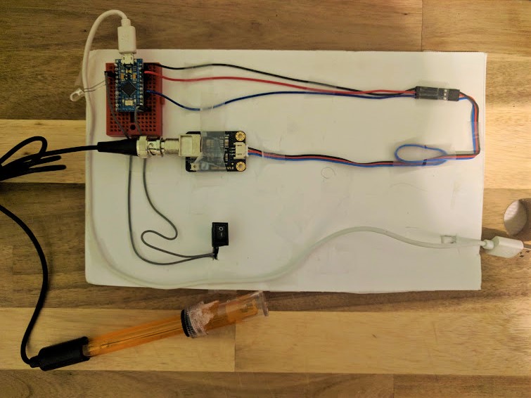
Required Materials
THE SENSOR This is the sensor that we are going to be using to collect data. FURTHER DESCRIPTION
The sensor plugs into a small board with a circuit. This board can be connected to your Arduino and simplifies the process of getting data from the sensor.
See the materials list in the series overview for other materials.
Step 1: Testing Your Arduino
Before we do any work building the circuit for our sensor or writing code for the Arduino, we want to make sure that the Arduino works on its own and that we can connect to it using our computer.
To test the Arduino, we need to install the Arduino IDE software, connect the Arduino to our computer, and upload a simple test program to verify that everything is functioning. If we do this before we do any other work then we will know that we are starting with a functioning Arduino.
For more detail see: Setting Up and Testing an Arduino.
Step 2: Connecting Your Sensor to Your Arduino
The SENSORNAME sensor consists of two parts, the sensor probe and the circuit board. This can be connected to each other and to your Arduino with the included sets of wires.
Step 3: Connect Hook-up Wires to Sensor Circuit Board
Step 4: Connect Sensor Circuit Board to Arduino
See this section in the overview guide for instructions.
The DF Robot analog sensors all share a common design so that they all connect to the Arduino in the same way.
Step 5: Upload and Test Code
For more information about the general process of finding and using Arduino code to work with sensors see this section in the overview guide.
The SENSORNAME GUIDE on the DF Robot wiki has sample code that we can use to get started. The most important thing to note about this code is that at uses the analog pin A0 to read input from the sensor. This means that we need to make sure we plugged our sensor's DATA (BLUE) wire into pin A0.
CODE GOES HERE
This code is pretty simple. It does just a couple of things:
-
We can copy and paste this code into our Arduino IDE and then use the "Upload" button to send it to the Arduino.
CODE IMAGE
If everything is working, some lights should blink on the Arduino we should see an "Upload Successful" message at the bottom of the IDE.

If you don't, you can refer to the "Troubleshooting" steps in the beginning of this guide that we went through when we first tested our Arduino.
Step 6: Read Sensor Values
Now that we've uploaded our code to the Arduino we want to check to see that we are getting data values back from our sensor and that these values make sense.
We can see the data being sent to our computer over the USB port using a tool in the Arduino software called the "Serial Monitor." You can access it through the "Tools" menu.

The serial monitor will bring up a window that looks like this.
IMAGE OF SERIAL MONITOR
SPECIFIC GUIDANCE ABOUT THE SENSOR AND DATA
Next Steps
Now that we know we are getting data that makes some sense and has some relationship to the sensor, our next steps are to calibrate it more precisely and take some measurements of actual liquids. We will go over that process in another research note.
Troubleshooting
If you _aren't _getting sensible seeming data, there are a couple of likely culprits.
- OTHER PROBLEMS
- If you are always getting a middling value that changes randomly without any regard for what is between the sensor probe, you have probably plugged the SIGNAL wire into the wrong pin of the Arduino. Make sure it is plugged into pin A0 and that the code you have uploaded to the board says **analogRead(A0) **to match.
- If you don't get any number coming in through the Serial Monitor, you have probably not successfully uploaded your code to the Arduino. See the **Testing Your Arduino **section for more information.
If you have any other problems, _please _leave a comment on this research note. I would love to help you debug the issue and add it to my troubleshooting guide!
0 Comments
Login to comment.