For couple of months I'm at Shanghai, working with DFRobot, a robotics and open source hardware provider company, to develop an open source automatic water quality monitoring device that could be used for Pearl River monitoring.
Background in environmental investigation NGO, my knowledge on electronic development is very limited. Hopefully this document could help people like me to easily understand and replicate such a tool.
KnowFlow is the name of this water quality monitoring device, based on Arduino Uno. It can automatically monitor 5 parameters of water: pH, Temperature, Dissolved Oxygen, Electronic Conductivity, ORP.
Currently, KnowFlow is powered by a 7.4V lipo battery, the data is stored in a SD card. The field test will be described in a separate research note.
DFRobot produces all the electronic components except for DO, which is produced by Atlas Scientific (btw, all the DFRobot's products are open source), most of the materials I listed are made by them.
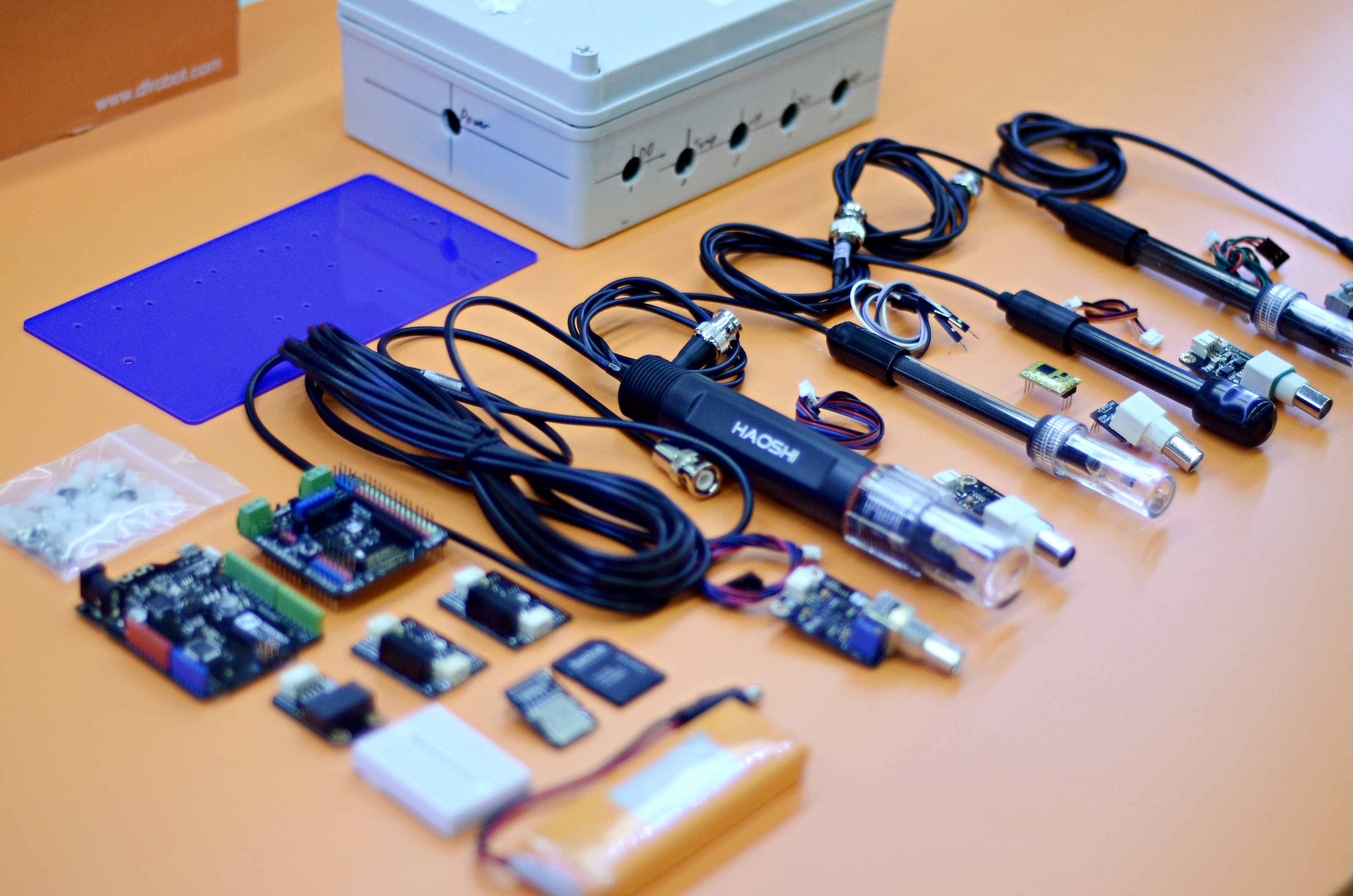
Prepare the materials

- Central Control Unit: Arduino Uno (DFRobot Bluno in this case) and Expansion Shield (DFRobot Expansion Shield V7.1 in this case)
- Water Sensors: pH (pH probe and pH circuit board); EC (EC probe and EC circuit board); ORP (ORP probe and ORP circuit board); Temperature (temperature probe and temperature circuit board); Dissolved Oxygen (DO probe, BNC and circuit board); real time clock circuit board
- Data Storage: Micro-SD module, Micro SD card
- Fit and fix: mounting plate, water proof box( 200mm_150mm_75mm), water proof joint
- Other parts: Cables (Wires), bread board, bolts and nuts, screws, battery, double-sided adhesive, write on tape, small wrench, spiral cable wrap
The size, modal, drawings, and other specifications of the materials can be found here at google docs.
Software
- Download Arduino IDE
- Download Knowflow code from KnowFlow github
- find "WaterMonitor.ino" from the downloaded file, open it with Arduino IDE
- Connect your Arduino Uno board, in menus, select "Tools - Board: Arduino Uno", and "Ports - /dev/cu.usb..."
- click "Verify", than "Upload" the software to your board.
Hardware
We need to connect all the sensors, MicroSD card module to the Arduino, then fixed it to the plate and the waterproof box, connected to the power supply.
Those who are familiar with the Arduino could directly read code annotation
1. Connect the circuit board and other modules to the Arduino expansion (I / O Expansion Shield V7.1)
- Connect EC: Plug one end of the "orange-red-black" cable to the EC circuit board, other end to the IN terminal of the isolation module. Plug the white end of the "blue-red-black" cable to the OUT terminal of the isolation module, the black end to Analog port A1, note the color should be matched.


- Connect the pH: Plug the white end of the "blue-red-black" cable to the pH data transfer board, the black end to port A2.

- Connect ORP: Like EC, Plug one end of the "orange-red-black" cable to the EC data adapter and the other end to the IN terminal of the isolation module. Plug the white end of the "blue-red-black" cable to the OUT terminal of the isolation module, and the black end to the A3

- Connection temperature: Plug the white end of the "green-red-black" cable to the Plugable Terminal V2, and the black end to Digital Port D5

- Connect the dissolved oxygen DO: The connection of the dissolved oxygen is bit complicated. Using four wires and breadboard to connect DO to the serial port (connection principle is GND-GND, VCC-VCC, TX-RX, RX-TX)


Note! Very important! Each time you re-upload the program to Arduino, you need to pull out the Rx (0) Tx (1) cable, and re-plug it after uploading. Otherwise it can not be programmed successfully.
- Connect the Real Time Clock (RTC) module: Plug the white end of the "blue-green-red-black" cable to RTC, and the black end to the blue I2C interface (you might need to wrap the line in case it's too long)
- Connect the MicroSD card module to the blue SD card slot (note the direction) and insert the Micro SD card

Great!!! All sensors are connected!
Tips: You can use the write-on tape to mark different sensors to avoid confounding, and wrap the analog cables and DO cables respectively to avoid clutter.
2. Place the mounting plate to the waterproof box
(The drawing of the mounting plate is here at GitHub )
Find the mounting plate, bolts and screws, install the hexagonal column to the small holes. The nylon column is mounted on the front of the board and the nut is mounted on the opposite side. Among which, the 4 Arduino fixing hole requires 6mm nylon column, which the rest requires 4mm nylon columns. You can use a small wrench to help tighten.


Use two 4mm screws to secure the board in the waterproof box. (Some waterproof box might conflict with the lower right column, it can be removed in this case)

3. Attach the electronic components to the mounting plate
- Since the DO module is more difficult to install, so we should install it first. (it can also be soldered). Attach the double-sided adhesive tape under the DO breadboard. Pass BNC interface from the circuit board through the hole, adhere the breadboard.

- Fix Arduino Uno, place the Arduino expansion board.

- Pass the BNC of ORP's circuit board though the rightmost hole of the waterproof box, fix it to the mounting plate with screws, install EC and pH in the same way.

- Adhere the two isolating modules to the top right of the mounting plate by tape.

- Fix RTC

- Now, only left temperature module. Tighten the waterproof connector to the round hole outlet of the temperature probe


- Then, the temperature probe has a bare end of the line, followed by waterproof connector cover and round hole,

- There are three "gates" in the front of the temperature signal adapter board. Press the button above, and the "gate" will open. Plug the yellow wire in the A gate, the red wire to B gate, black wire to C gate. Try to pull out the three wires respectively to make sure there're fastened after plugging in.

- Use a screw to secure the temperature signal adapter board to the board and tighten the waterproof connector nut on the housing.

- In-box part is completed, now connect the battery to test whether the installation is correct. If the light turns on, it means that the circuit is normal.

- Close the box and connect each probes.

Done!

The field test of this device will be written in a separate research note.

62 Comments
So cool!!
Reply to this comment...
Log in to comment
Thank you for these well-written and elegantly photographed instructions! I found this note very inviting and i can't wait to order the parts and make one! @bronwen, can we order a set of these parts for NYC?
Is this a question? Click here to post it to the Questions page.
Reply to this comment...
Log in to comment
Absolutely, @liz ! This is a really exciting (and well documented!) research note. Thanks for sharing, @shanlter !
Reply to this comment...
Log in to comment
@Bronwen awards a barnstar to shanlter for their awesome contribution!
Reply to this comment...
Log in to comment
@bronwen, @liz, am I wrong or this could be considered as "method"? It's own particularities made the KnowFlow a different one than Coqui, Riffle or Mae d'aigua. I'm basically thinking about the possibility of using a tag like "activity:knowflow" to facilitate builds and its tracking. Mmmm water monitoring tools spreading ;)
Is this a question? Click here to post it to the Questions page.
Reply to this comment...
Log in to comment
Thanks for saying so @xose! Compared with Riffle or Mae d'aigua, this one is much simpler, we use Arduino board, haven't do many field test yet, etc. It'll be improved, meanwhile hoping more people could join the developing process :)
Reply to this comment...
Log in to comment
Thanks @liz and @Bronwen, if you are going to order the parts from DFRobot, let me know. The isolation module been used hasn't been online yet (but soon), also the box and mounting plate I can mail to you together.
Reply to this comment...
Log in to comment
@xose - i've tagged it as an activity, but if other related (next steps) activities were added, and a Q+A section, this could be the first post on a Methods page, for sure! See how we've started to build that for the https://publiclab.org/wiki/nano-data-logger -- and if you want one for the #orange-pi camera, that's a great idea!
Reply to this comment...
Log in to comment
Wooow!! Great @warren! I'm having some troubles with the orange pi by now. This week we'll lift up a raspberry 2 with both a drone and a ballon. Let's see what happens. Orange pi is awesome. As soon as I got something I'll be back. The main issue by now with the orange one is low camera compatibilities and the one I got is just 2megapixels. Let's see what can we do ;)
Reply to this comment...
Log in to comment
@xose - awesome. And even "having some troubles" is ok to post -- if we break out the issues perhaps there are folks who can chime in with solutions. Thanks!!
Reply to this comment...
Log in to comment
This is great! I'm starting an effort that will involve the parallel build of a simple in situ data logger (e.g. Riffle or maybe Cave Pearl) and a slightly simpler version of the KnowFlow (only PH, ORP, and EC). The hope is that these can be finished in time to sample at the same time/locations as some EPA supported sampling this fall. The parts for the KnowFlow-esque are going to be ordered from DFRobot and was wondering if you could point me toward the appropriate 'isolation module'? Thanks! Dave
Is this a question? Click here to post it to the Questions page.
Reply to this comment...
Log in to comment
Hi @MadTinker, thanks for your question! I just saw your questions around dataloggers for pH! I think DFRobots' isolation module is not online yet (but soon), I'll ask them for more details tomorrow and get back to you. Also, @Rockets is the engineer from DFRobot :)
Reply to this comment...
Log in to comment
@MadTinker, according to my knowledge, the reason why to use "isolation" is to avoid interrupting between sensors. Both OPR and EC need isolation. Other options include Atlas Scientific's (https://www.atlas-scientific.com) "isolated board", however it does not compatible with DFRobots' sensor. (btw, Atlas has all the sensors you need as well). DFRobots can lend you the isolation module if you want, since it is not for sale yet. and when you finish using, you can give back to PL's lending library (there's no such thing not yet, but according to @bronwen will happen soon)
Reply to this comment...
Log in to comment
@shanlter did you have the opportunities to talk with dfrobot team?
i have purchased a ph shield from them, and after some experiment i noticed that without isolate salinity reading are just impossible due to noise from EC (same apply on the opposite obviusly)
multiplexing them, doesn't help much, isolation it's the only way i think :(
so the isolation circuit will be very very very (very very) handy :D
Is this a question? Click here to post it to the Questions page.
Reply to this comment...
Log in to comment
@ramarro totally agree! When I first use their sensors, I also have the same problem. I asked them and was told to use several Arduino boards for each sensors....But now I think they are fully aware this problem ... Did you also buy EC from them? I have one problem with their EC is that it can not detect low concentration, what kind of water are you testing?
Is this a question? Click here to post it to the Questions page.
Reply to this comment...
Log in to comment
@shanlter using 2 arduino (or 20) doesn't change anything, unless you use galvanically isulated ac/dc converter.
if you power them from the same source, you got interference in any case. Of course you can power them with 2 different batteries, but you have to handle a lot of different wire.
for the EC, no, i don't use the one from dfrobot. i use this https://github.com/cyberplantru/EC-mini-v31-hardware/blob/master/EC_mini_v31.pdf it's very simple to do made and work decently.
what's the K(cell constant) of the dfrobot probe? i use mine on saltwater aquarium, my target it's 53.065 mS/cm
Is this a question? Click here to post it to the Questions page.
Reply to this comment...
Log in to comment
i forget to add some details :)
even if you use 2 arduino, at least in my scenario, and u want them communicate in some way, you have to use a common ground, that still give me problem of noise.
i have try with an esp8266 to make a wifi module version for ec, powered by battery, but the power usage of esp8266 it's too high to have a set-it and forget solution (or at least a montly checked one)
that's my findings till now :)
if we can have a real isolator (not just an octocoupler, but something that isolate vcc and gnd too, then everything will be much much easier, even with ph/orp/ec all togheter.
as a note, how do you find atlasscentific things? i don't like much the protocol of this things, and the price it's quite intresting :)
are you aware of a way to measure dissoved co2? this will be a game changer for a reef aquarium :) co2 with ph = kh. kh it's one of the most important params for a reef, and one of the less stable :)
what do u have? (speaking about aquarium)
Is this a question? Click here to post it to the Questions page.
Reply to this comment...
Log in to comment
@shanlter A little confused about what you used for EC. The KnowFlow spec sheets indicates a DFRobot EC sensor, but in the above you indicate some issues with the DFRobot EC sensor and that you use a custom EC_mini_v31 Is the latter the currently preferred sensor?
Is this a question? Click here to post it to the Questions page.
Reply to this comment...
Log in to comment
@MadTinker,
@shanlter use DFRobot EC probe. I am using EC_mini_v31
we are two different person :) using 2 different devices for a similar project (both try to monitor an aqurium/pond/something like that) and was exchanging some comment about that.
notice that the nickname on the EC_mini_v31 it's mine not shanlter :)
Reply to this comment...
Log in to comment
@shanlter @ramarro Dang, got lost in the comments .... my bad.
Reply to this comment...
Log in to comment
@ramarro, you tried so many stuff! Thanks for the info on EC, I am learning it. Lots of the questions you mentioned I don't know the answer, I asked yoyo (the main developer of DF's water sensor) to reply here directly, hopefully he will come. I use this thing to monitor river pollution, I used to test KH by test strips but didn't give much attention to this parameters. Speaking of Atlas, the parameters they chose looks to me are more for general river monitoring other than aquarium, what do you think? I only tried their DO, it's too expansive (especially because I'm in China). I don't like their design as well. I have to either use bread board or soldering pins, not beginner friendly...
Is this a question? Click here to post it to the Questions page.
Reply to this comment...
Log in to comment
Yes, you got it :) @MadTinker If you want to use DFRobot's EC sensor, you'd better test your sample with a TDS pen first (which only costs several dollars), if it is less than 200 ppm, DF's EC might be useless.
Reply to this comment...
Log in to comment
@shanlter i think that DFR EC will be better than what i use, at least after a brief look to the circuit. i will order one, and try it as well, if they add to the store (or even in an unofficial way) the mighty isulator circuit :)
personal observation: if you use arduino ADC, it's 10bit, from 0 to 1024. this on a 5V lead to a precision of 0,0048828125 -> 4mV
from code on dfrobot 1
averageVoltage=AnalogAverage*(float)5000/1024;2
if(CoefficientVolatge<150)Serial.println("No solution!"); //25^C 1413us/cm<-->about 216mv if the3
if(CoefficientVolatge<=448)ECcurrent=6.84*CoefficientVolatge-64.32; //1ms/cm<EC<=3ms/cmso, with a 4mv of precision, results well... will sucks :D i think that there will be more than 10% of error.
you can use a super cheap ads115 16 bit adc, i purchase it on aliexpress (and don't complain, living in china it's cool for this kind of things hehehe) for 2$ i think. 16bit will give you much better results. you can also compensate VCC fluctuation, connect in A0 you power source (5v) in A1 the ec analog out, do a differential read, and use this one to do all the calcs. if A0 fluctuate (battery drain, power fluctuation) A1 will fluctuate too, differential should have minimum impact. i do that for ph, and it's pretty good
let me show you the GUI of my controller
https://ibb.co/d6pjkF https://ibb.co/jEs4kF https://ibb.co/cnB8Cv https://ibb.co/dqSRza
as u can see, ph it's stable (with a 16bit adc) salinity with the EC (and galvanically isolated on a different controller) it's still not good. i think that ec-mini-3 design can't lead to good results (salinity to ec formula ti's something like Nx0.66, so 36ppt should be 56ms/c). as you can see it swing of 2ppt lower (unlikely, in a reef aquarium it's a stable parameters, evaporation should RAISE it, not LOWER it obviusly)
Reply to this comment...
Log in to comment
I just try translate youyou's answer into english.
Q:The parts for the KnowFlow-esque are going to be ordered from DFRobot and was wondering if you could point me toward the appropriate 'isolation module'? Thanks! Dave A:isolation model have been developed. Now we are doing the the online store process. Maybe you can get the model some time after months. You can find it in our online store www.dfrobot.com
Q:using 2 arduino (or 20) doesn't change anything, unless you use galvanically isolated ac/dc converter. even if you use 2 arduino, at least in my scenario, and u want them communicate in some way, you have to use a common ground, that still give me problem of noise. A:if you use two arduino, but use only one battery is not enough. You have to use two separate battery. If you need comunication with two arduino, use a wireless way such as bluetooth, never use a wire to do that. Or you can use a simple way to do that, test the water in diffent contorer, than you don't need use a isolation model.
Q:what's the K(cell constant) of the dfrobot probe? i use mine on saltwater aquarium, my target it's 53.065 mS/cm A: we are using a model which is using in lab. the K is 1.0, test range is under 20ms/cm. in your case 53.065, you have to use a K=10.0 probe which we don't have it. If you can provide more information for us something like what kind of water you want to test? where you use it? that will help us to development.
Q:if we can have a real isolator (not just an octocoupler, but something that isolate vcc and gnd too, then everything will be much much easier, even with ph/orp/ec all togheter. A: Yes, I have to say that our isolation model is a "real isolator". the isolator is divid into two part, A,isolator power. B,Optocoupler isolation. isolator power is used to isolate the power which are VCC and GND. Optocoupler is used to isolate the analog signal. because of the power and signal are isolated so it is a real isolator.
Is this a question? Click here to post it to the Questions page.
Reply to this comment...
Log in to comment
Thanks @rockets! I hope this could help answering your questions, @ramarro. btw, The GUI of your controller looks so nice! Where can I learn more about your project?
Is this a question? Click here to post it to the Questions page.
Reply to this comment...
Log in to comment
DFR0504_Analog_Isolation_Module-V1.0-_Schematic.pdf
here is the schematic of the isolator.
Reply to this comment...
Log in to comment
@shanlter i havent wrote anything about my project its just an hobbies for my aquarium :)
@rockets I am using my project to control my reef aquarium. that's why I need a k10 probe. salinity in reef its 53ms/cm as said. also standing to comment on the website I am not the only one :)
Reply to this comment...
Log in to comment
@rockets Thanks for the summary. I thought I was going to have to move in a different direction, but this clears things up. Cheers.
Reply to this comment...
Log in to comment
Hi @xose , @shantler did create a method page, and this now appears there as an activity! Check it out: https://publiclab.org/wiki/knowflow
Reply to this comment...
Log in to comment
@shantler @rockets et al... FWIW - I ordered the (majority) of the parts needed for a KnowFlow related system (sans the DO sensor and the enclosure) along with a Riffle kit. I'll be putting together a separate EC sensor for the Riffile and will eventually need enclosures for both. The project involves the deployment of the sensors and not just the build. Is a Wiki the best place to document this effort (assuming there is interest)?
Is this a question? Click here to post it to the Questions page.
Reply to this comment...
Log in to comment
@MadTinker, awesome!! I'm trying to get familiar with Public Lab's logic as well, I guess the best way to document is by replicating an activity? According to @Liz told me.
I'm not tech people as you can see, but if you have any problems when building it, I am more than happy to offer help. Also, if you could email me (i@shan.blue) or @rockets (rockets.xia@dfrobot.com) your address, DFRobot will lend you their isolation module as they promised.
Is this a question? Click here to post it to the Questions page.
Reply to this comment...
Log in to comment
Hi @madtinker, oh there's interest! as @shanlter said, the best place to document your build is by clicking the blue button "Click here to replicate this activity" right above this comment section here on this page. Since no one has yet documented deployment, consider posting a new note about your work on that via publiclab.org/post
how does this sound?
Is this a question? Click here to post it to the Questions page.
Reply to this comment...
Log in to comment
@liz Sounds great. I think there are three parts and I'll probably ask for advice on posting as things develop: the build, the deployment, and the comparison of sensors (which will be distinct from deployment) . On travel for the next couple weeks so will be quiet for a bit.
@shantler Thanks for the offer of the isolator circuit. I'll send address to both you and @rockets. I was already trading stuff for someone to build circuit. Thanks in advance.
Reply to this comment...
Log in to comment
@shantler @rockets FWIW- came home today with a mailbox literally full of 'stuff'. Also, many thanks for the loan. I have to track down my Riffle order, but everything else looks great. A bit of catch-up from being gone and I should be ready to jump in.
Reply to this comment...
Log in to comment
@shantler I'm probably missing something, but the battery shown in the link in the components list doesn't look like the battery in the pictures above. Is it possible that the battery you are using is actually this battery from DFRobot ?
Is this a question? Click here to post it to the Questions page.
Reply to this comment...
Log in to comment
@MadTinker I think you can use that, but if you have a power bank, that also working.
Reply to this comment...
Log in to comment
Hi @MadTinker , yes you are right, the battery I'm using is the one in your link. But you can use any kind of portable battery to charge your device, which is easier to find in any electronic shop.
Reply to this comment...
Log in to comment
@shanlter @rocket Thanks for the suggestion of the power bank. My biggest question, particularly related to the power bank in the link, was the voltage requirement of the KnowFlow. The DFRobot power unit was a 7.4V 2500mAh, while the item in the link was unknown (maybe 3.7V?). I also looked at a few power banks for the iPhones and the voltage for those was generally unspecified, but likely 5V.
Is this a question? Click here to post it to the Questions page.
Reply to this comment...
Log in to comment
Hi @MadTinker, I was told that 5V is fine, the board can automatically convert the voltage.
Reply to this comment...
Log in to comment
hi @madtinker, I know what you worry about it. I will say that the power bank is oK, since the main board is arduino uno. The power input will be 2 ways, the usb will be accepted by 5v which is almost all of the usb power bank use. the other input is for the battery like li-battery which is from 7.4~12v. If you use a li-battery like 7.4v, the voltage will be low to 5v by the chip on the board. So don't worry about it. Both them will be ok. And I think I will put your question into FAQ. Would you mind me to do that?
Is this a question? Click here to post it to the Questions page.
Reply to this comment...
Log in to comment
@rockets Yes! that is exactly what I was concerned about. I'm too new at this to figure out what's an intelligent Uno question. I think a fundamental bit of confusion I had related to the difference between the voltage in at the barrel plug and the voltage in at the mini-USB. This is my understanding: the barrel plug requires greater than 5V since the power is conditioned down to 5V. If it is exactly 5V, the Uno ends up being underpowered. The micro-USB takes in exactly 5V since that is the established standard, controlled voltage from a traditional USB port on a computer. My question is really: can I use a 5V power pack on the barrel connection. It seems that you think it's okay. Which is perfect for my application so I hope that it is correct.
I'm trying a bunch of combinations. I purchased a Standard USB to barrel cable to test using an iPhone-type power pack. I also purchased the same 7.4V power pack and charger that @shanlter used (per pictures). [I sell blacksmithing items to finance my Watershed Reclamation efforts - had a good chunk of sales over 4th of July so I'm splurging a bit on stuff.]
No problem with you putting the notes in the FAQ. Very much appreciated.
Reply to this comment...
Log in to comment
@shanlter Would you mind posting a PDF version of your DWG layout that you have on GitHub? For some reason, none of my code can read the file. Thanks a bunch!
Is this a question? Click here to post it to the Questions page.
Reply to this comment...
Log in to comment
@MadTinker, I uploaded a pdf to github. There are 2 drawings, one is the mounting plate which should be printed by a laser cutting machine. It's not necessary, find a normal board and tape your components to it is enough. Another one is the water proof box, the size and number is for your reference. : )
Reply to this comment...
Log in to comment
@shanlter Awesome, Thanks for both!
Reply to this comment...
Log in to comment
@shanlter @rocket Unfortunately, I was/am in a time crunch and just followed the parts list put together by @shanlter without cross checking it with the assembly instructions. I've already ordered the LiPo battery and charger. Seems to be a couple of other issues: SKU-FIT0348 on the parts list is not the PH sensor in your discussion. Not a big deal (beyond being expensive), but it doesn't come with data adapter and cable. Is the correct part: SKU-SEN0161? Also, since I have to put in another order to DFRobot, are there 'orange-red-black' cables available? (local hobby store doesn't seem to carry them.)
EDIT: or possibly SKU-SEN0169?
Is this a question? Click here to post it to the Questions page.
Reply to this comment...
Log in to comment
@MadTinker obviously you order a wrong one, you should order sen0169, I will help you to solve it. Don't worry.
Reply to this comment...
Log in to comment
@rockets Yeah, I was going too fast and assumed that the parts list was good. I still need to order the ORP SEN0165. If you can tell me the SKUs for: - the data adapter and cable to bring what I have up to the SEN0169 and - the cables for the two isolation modules, then
I'm okay with paying the difference and having them all shipped at the same time as the ORP.
Reply to this comment...
Log in to comment
@rockets Have you had a chance to check on the cables for the isolation boards? I very (very!) much appreciated the loan of the two boards, but without the cables there is not much i can do.
Also, FWIW, I've ordered the ORP package and the other, more complete, PH package. It was going to cost me $50 to return the other PH sensor so I've decided to just hang on to it and treat it as a spare.
Is this a question? Click here to post it to the Questions page.
Reply to this comment...
Log in to comment
@Madtinker I have send a mail to you, let me know the order no. so that I can put the cable to you.
Reply to this comment...
Log in to comment
@rockets Got the cables today. Thanks!
Reply to this comment...
Log in to comment
Everbody we have checked the github, we found that the github code have some problem, then we fix it. So now maybe you can use it now.
Reply to this comment...
Log in to comment
Thanks @Rockets !
Reply to this comment...
Log in to comment
@Madtinker how about your project? Anything we can help?
Is this a question? Click here to post it to the Questions page.
Reply to this comment...
Log in to comment
@rockets Well.... a lot of possibilities for lessons learned. The good news is that between binges of travel, I spent a bit of time getting (somewhat) familiar with Arduino programming. It's both easier and more complicated than anticipated. The bad news is that yesterday I felt confident enough to start put all the pieces together and discovered that the Real-Time Clock on the original KnowFlow parts list (TOY0021) was the incorrect. Ordered the correct part (DFR0469) yesterday and that should be here in about a week or so. I noticed that the KnowFlow parts list has also been updated. In the mean time, I'm going to try to get a GPS unit incorporated into the system. Haven't even started that yet, but would appreciate any thoughts on issues that might arise. Cheers.
Reply to this comment...
Log in to comment
Hi @MadTinker, I feel very sorry for RTC (also for the cable, and many other things...) When I make this guideline, DFRobot did't have the RTC I'm using in their store yet, and I was told it can be replaced by another older one. But soon, the new product released, and I didn't update the list in time. BTW, will you go to Public Lab Barnraising at Louisiana? I'll go. so I am thinking maybe I could drop by your place in October and bring you some of knowflow's new designs.
Is this a question? Click here to post it to the Questions page.
Reply to this comment...
Log in to comment
@shanlter No worries, things will work out fine. I won't be at the Barnraising, I'm already committed to attending a training class for Colorado River Watch (http://coloradoriverwatch.org) and won't have resources to attend both.
Reply to this comment...
Log in to comment
@MadTinker, I just take a look of the Colorado River Watch training, it looks very interesting and I want to learn how Colorado people monitor the water. Do you think I can apply for the course? (or maybe I should email the organizer to ask since obviously I'm not going to join Colorado river watch in the future...)
Is this a question? Click here to post it to the Questions page.
Reply to this comment...
Log in to comment
@shanlter I've gotten everything connected and the initial tests are good.
Reply to this comment...
Log in to comment
@Madtinker Can you find the code like below? You may change the setting here to make the RTC in your loc time.
Is this a question? Click here to post it to the Questions page.
Reply to this comment...
Log in to comment
great project, can you guy help me monitor the signal wirelessly
Reply to this comment...
Log in to comment
Hi @mrkhan1994 Thanks for your interest, I haven't tried, but I know @rockets have used this iot module to get data wirelessly (it need wifi tho). https://www.dfrobot.com/product-1674.html
Reply to this comment...
Log in to comment
Hi I would love to build a system just like this but I am concerned that the github libraries are over 4 years old and look like they are not manintained. Has this project/code been superceded by something else? Thanks
Is this a question? Click here to post it to the Questions page.
Reply to this comment...
Log in to comment
Login to comment.