What I want to do
Ben Gamari had implemented an ingenious version of the Riffle hardware that measured the conductivity of water (aside: for a great tutorial on conductivity in a water quality context, pointed out to me by Jeff Walker, check out this Fondriest guide) by exploiting the properties of an old chestnut of an integrated circuit: the '555 timer'. I'm looking to breadboard a similar circuit myself, in order to understand the basics of how this setup works.
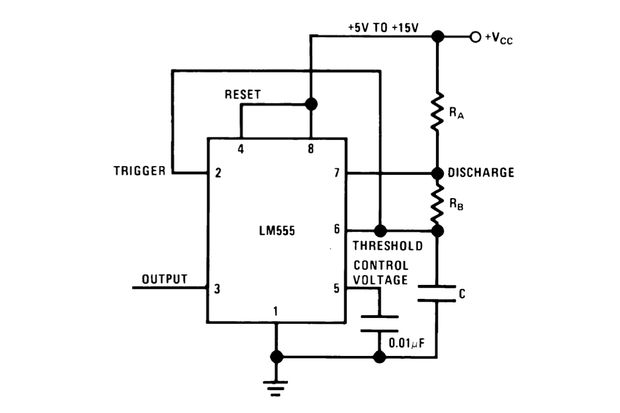
 Figure A: 'Astable' wiring diagram for a 555 timer.
When a 555 chip -- which costs $2 at RadioShack, but is available widely online for much cheaper -- is placed in a particular circuit configuration (dubbed the 'astable' configuration) that involves a capacitor, C, and two resistors, RA and RB, all wired up a certain way, the 555 produces an output voltage (on its 'output' pin) that oscillates between high and low voltage values (where high = the input voltage, 'VCC', and low=0 Volts), with the following frequency:
f=1/(0.7(R_A+2R_B)*C)
where: - f is in Hertz (cycles per second) - R_A and R_B are in Ohms - C is in Farads.
Note that if you're wiring up a 555 on a breadboard and following Figure A above, the 555 pin numbers are actually arranged counter-clockwise, starting at the 'top left' of the 555, as in Figure B below:

Fig B: The typical pinout on a 555 IC.
My attempt and results
For example, I just now breadboarded this arrangement, and used the following values:
- R_A=21000 Ohms (i.e., a 21 kilo-Ohm resistor);
- R_B=2300 Ohms (a 2.25 kilo-Ohm resistor);
- C = 0.000047 Farads (a 47 uF capacitor)
Plugging these values into the above equation for the frequency, 'f', we get f = 1.2 seconds -- which is about the frequency I observed when I connected an LED on the 'output' pin.
Why I'm interested
The motivation for this exercise is the following: due to the straightforward relationship between the resistor and capacitor values in this 555 circuit and the oscillation frequency of the 555 output, we can use this circuit to measure the resistivity (and, thus, the conductivity) of water. The idea is: set up the above circuit with known values of R_A and C, but connect wires ('probes') from the circuit through a water sample so that the water is the 'resistor' R_B. By measuring the frequency of oscillation of the 555 output, we can back out what the effective resistance, R_B, must be between the probes.
In lieu of using a water sample, I tried out this idea with a 10 kOhm photodiode, and took a video of the result:
Next steps
- Find a nice way of measuring the frequency of this oscillation using simple Arduino code
- Try this out with a water sample, using appropriate values for the R_A and C, such that we end up with an oscillation over around 1 kHz (the frequency range above which the effects of our cicruit on the water electro-chemistry -- e.g. shifting ions around in the water -- will be sufficiently minimized)
12 Comments
This is really cool. I would never want to discourage someone from using a 555. And it would be totally sweet to use audio gear to record and imagine changes in resistance using the 555 as an oscillator.
BUT-- I don't think you need the 555 unless its frequency generator functions as a sort of amplifier for a weak signal. I doubt that this is useful though. I think you can do it directly through your system's ADC.
The 555 uses a voltage divider to set the frequency based on the divider's ability to step down voltage. An ADC can already measure voltage, here's arduino code for getting back to a voltage from a raw data input. With that, you can use the voltage divider equations in the wikipedia page to solve for the unknown resistance of the water.
Reply to this comment...
Log in to comment
Ah -- great thoughts! And your comment points to an important issue, which is that I myself was unclear (and still am, a bit) as to the utility of the 555 for this purpose :) I'm still learning as I follow Ben's lead, but here are some (perhaps relevant) things that I only as yet vaguely understand:
we want to put very little current through the water, both in order to conserve battery power, and in order to avoid polarizing the water around the electrodes. using the 10 bit Arduino ADC to distinguish such weak voltage signals might be hard (i think?). this sort of echoes your suggestion that there's an 'amplifcation' rationale for the 555, here: we can set up a trigger in the Arduino code to fire every time the oscillating 555 signal reaches VCC, with a time resolution of microseconds, which should be sufficient for the 1kHz frequency we're shooting for ...
the ADC on the Arduino is optimized for impedance of 10 kOhm or less -- much greater than that, and the voltage used to make the measurement may 'droop', and throw off the measurement (I think). The resistance of tap water, between two steel electrodes 2 cm apart or so, seems to be in the mega-Ohm range. There may be ways of addressing this dropping with op-amps though, I think ...
whatever signal we use to measure the resistance we'll want to do in an oscillatory fashion, ideally above 1 kHz or so, so as to avoid polarizing the water (by shunting ions towards one of the electrodes) and plating / corroding the electrodes over time. The 555 method helps in this regard, too ...
all that said, there's a simpler approach than the 555 that satisfies all of these constraints, too: placing a capacitor in series with the water, then charging up the capacitor, and measuring the amount of time it takes to charge to a given voltage threshold -- this time will be related to the resistance of the water. This is what the K20-based Riffle does currently, but there are some tricks involved in getting the auxiliary circuitry right, and I'm trying this easier-for-Don-to-grok-for-now 555 approach just to get something working ... eager to try this other way of doing things soon, though ...
Is this a question? Click here to post it to the Questions page.
Reply to this comment...
Log in to comment
the 555 is pretty simple. There's not that much inside of it. If it simplifies the power circuitry issues you're facing then go with it. I hadn't thought about the oscillations being important either, but I don't see how that solves the polarization issue-- the signal coming out will oscillate, but you're taking DC in.
I guess I'm wondering why the electrodes have to be 2cm apart, also remember that you're not measuring impedance of the water, you're measuring it in series. By playing with the other side of the voltage divider you could probably adjust for this issue.
I'd go for the capacitor method. I think the power consistency issues you're facing will be almost identical with the 555.
Reply to this comment...
Log in to comment
Egads! Mat, thanks for pointing this out! I totally flubbed that one: in the 555 approach, the signal that is passing through the water is indeed DC, as you say; it's the oscillatory signal coming out of the 555 (and not going through the water) that we're measuring. I think in my head I was conflating several discussions with Ben around more than one method, as well as some discussions l'd had with Julian Tyson about potentiostats (also only vaguely understood).
Good point on the 2cm apart figure for the electrode spacing -- I'm now playing with a metal screw configuration that places the screws 1 cm apart -- and they could like be placed .5 cm apart without any extra tricks ... I made a dumb little circuit board that holds the pressure / temp sensor we'd selected, and has some holes that are suitable (i think) for m3 screws: https://github.com/p-v-o-s/riffle-ito/blob/master/riffleito-CTD-REVA-board.png -- if it works, the closer spacing would be around 4 mm apart ...
Yeah, the capacitor method seems cheapest / simplest / lower power -- and if the power issues are the same as with the 555, then why not ... I should ping the better Ben brains on this one ...
Reply to this comment...
Log in to comment
the power issues are going to be tough. Most power control chips do tricky high-speed things to push out a DC signal and the voltage isn't very clean. A dedicated battery for the sensor will give a nicer DC signal. my suggestion is to research audio equipment. Somewhere there is an audiophile electronics nerd with a portable headphone amp design that will give you the clean, consistent AC power signal that you're looking for.
I'm also going to re-iterate my earlier suggestion of using a 1/8" mini-jack for conductivity, it'll give you 2mm spacing.
Reply to this comment...
Log in to comment
Good call on the power control chip -- for the riffle-ito design, I'm just using an LDO, which should provide a relatively clean signal? But yeah, there is some op-amp trickery that Ben is expert in that I need to grok soon ...
TOTALLY SPACED on the awesome 1/8" mini-jack idea!! I need to order some right now.
Also: do you have any leads on a simple tutorial / breakout for generating an audio signal from e.g. an UNO? I'm looking to play with 'audio out' -- e.g. just play back the last week's worth of conductivity data as an audio signal -- so folks could tell immediately whether the conductivity history over the last week was 'spiky' or 'smooth' ... i'm imagining a daily 'metronome beep' for reference ... and maybe folks could even record the data onto a smartphone via an audio cable, for later upload to a site ...
Is this a question? Click here to post it to the Questions page.
Reply to this comment...
Log in to comment
E.g. I just found this: http://wiki.openmusiclabs.com/wiki/PWMDAC And, oh gosh, this is fun: http://sensorium.github.io/Mozzi/ And: http://www.uchobby.com/index.php/2008/01/08/arduino-audio-dac-options/
oh my.
Reply to this comment...
Log in to comment
Wow, i'm not sure I follow all of this, but is one potential advantage of the 555 that we could even skip the arduino entirely, if, say, we wanted the output to be solely a blinking light or a beep, which could be read over the audio channel into a smartphone or laptop?
Is this a question? Click here to post it to the Questions page.
Reply to this comment...
Log in to comment
Yes, exactly! I would love to see an analog "retro edition" riffle with a microcassette recorder and a 555, maybe in a really nice Ball jar.
Reply to this comment...
Log in to comment
ZOMG that's brilliant. I'm going to try to bring the materials required to do a rough prototype of this to Plymouth -- but anyway shouldn't be hard to try out one way or the other!
Reply to this comment...
Log in to comment
Also: how hard would it be to rig up some sort of 'pen' that connects to a 555 and writes out a 'record' of the conductivity on some physical medium? Writing onto a paper strip like a seismograph is cool -- but maybe difficult? Is there some other way to translate a changing voltage into something that creates a 'written record'; -- even if it only lasts for a few days? Sand patterns on surface vibrated at these frequencies? Some other material vibrated that would show a 'history' -- like corn starch and water?
Is this a question? Click here to post it to the Questions page.
Reply to this comment...
Log in to comment
WARNING: do not, under ANY CIRCUMSTANCES get distracted by searching e-bay for vintage Hygrothermographs.
Reply to this comment...
Log in to comment
Login to comment.