
Image above: Lab assistant operating the SpectroBench 2000.
Introduction
I thought it was going to be easy to build a new version of the Public Lab spectrometer, but some discussion at the PLOTS-spectrometry group and some comments on research notes made me doubt my understanding of how distance between the entrance slit and the grating, or the angle of the grating, affected performance. So I built an optical bench to observe how these things interacted.
Methods
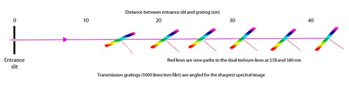
I used 1000 lines/mm grating film for the diffraction grating. The entrance slit was formed from the facing edges of two box cutter blades, and I tested two different slit widths of about 0.15 and 0.25 mm (these slit widths are too narrow for me to measure accurately). A second trial at about 0.25 mm was made after readjusting the width, so width might have differed between these trials. I moved the grating along the optical bench in 1-3 cm increments so it was from 14 cm to 45 cm from the entrance slit. At each position I rotated the grating until the image of the spectrum of a compact fluorescent lamp appeared to be sharpest. I measured the angle of the grating (g) with a Starrett machinist's protractor with 1° gradations. I also recorded the angle at which I was looking at the grating (v) to view the sharpest spectrum. This was the angle between a line perpendicular to the slit-grating axis and the line from my eye to the twin mercury lines at 578 and 580 nm.
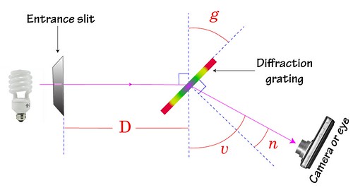 Schematic for the bench measurements. I varied the distance between the entrance slit and the grating (D) and at each distance measured the angles g and v which revealed the sharpest spectrum. Angle n was calculated as |90-(g+v)|.
Results
The angle at which the grating must be positioned for the sharpest spectral image varies between 45° and 66° depending on the distance between the entrance slit and the grating. The angle at which the grating must be viewed for the sharpest spectrum is not perpendicular to the grating, and varies with distance from the entrance slit.
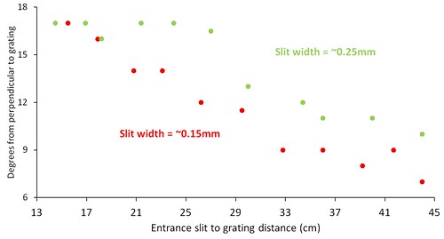
 The grating angle (g) that produces the sharpest spectral image, and the best angle for viewing that image (v), depend on the distance between the entrance slit and the grating (D). These results are for an entrance slit of 0.15mm.
The relationship between slit-grating distance and grating angle appears to be non-linear. Both grating angle and viewing angle are most sensitive to slit-grating distance at the near (14-20 cm) and far (40-45 cm) ends of the distance range tested.
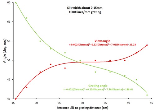 Grating angle (g) and view angle (v) using a slit width of about 0.15 mm. The grating angle for the sharpest spectrum depends on the distance between entrance slit and grating, and is most sensitive to distance at the near and far ends of the range tested.
The two trials with a slit width of about 0.25 mm did not produce highly similar results. However, the general pattern of the grating angle approaching 45° as slit-grating distance approaches 50 cm was confirmed.
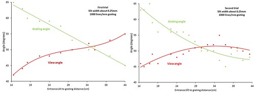 Replicate trials of angle measurements using a slit width of about 0.25 mm.
 Viewing the spectrum so that the mercury lines at 578 and 580 nm are centered in the image requires a view angle that is not perpendicular to the grating. The angle approaches perpendicular as the slit-grating distance approaches 50 cm.
 Offset from perpendicular (to the grating) for the viewing angle for trials with two slit widths. This is angle n in the schematic above.
Discussion
Physical explanation for these results. I am a biologist. I have no idea how to explain these results.
Implications for spectrometer design. Grating angle is most sensitive to variations in slit-grating distance for the shortest (14-20 cm) and longest (40-45 cm) distances tested. A medium distance of about 30 cm might make it easier to find a grating angle that produces a sharp spectrum. This angle is about 50°.
Results for the wider entrance slit (0.25 mm) were less consistent than for the narrower slit. This might be because a narrower slit requires a more precise grating angle, and it was obvious to me when the grating had been rotated to that angle. A wider slit produces a sharp spectrum over a larger range of grating angles, so it is harder to determine the optimum angle. Therefore, building a spectrometer is easier with a wider entrance slit because precise alignment is less critical. But if the optimum angle for a narrower slit is found, the spectral peaks will be better resolved.
To view the visible light spectrum when the grating is rotated for maximum sharpness, it is necessary to look at the grating at an angle other than perpendicular to it. For a slit-grating length of about 30 cm, the best view is about 10° from perpendicular. This suggests that the camera in a spectrometer should be aimed at this angle. However, the typical camera lens has a sufficiently wide angle of view and collects light from a range of incident angles, so this adjustment might not be important.
Conclusions
A reasonable design for a spectrometer might have the specifications illustrated below.
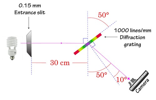 Proposed design specifications for spectrometer.
14 Comments
Amazing. Two questions:
Wonderful!
Is this a question? Click here to post it to the Questions page.
Reply to this comment...
Log in to comment
Oh, almost forgot my other question! Do the camera lens and aperture make any difference at all? You didn't use a camera for this... could you try it out with a webcam?
So for the instructions in the DSK, your point is that actually the camera should not be aligned perpendicularly to the grating, because doing so makes the ideal grating/slit distance huge?
Let me rephrase -- shall we try a modification of our existing DSK design by tweaking:
in order to achieve the best focus for a basically fixed distance between the grating and the slit, which is ~8-10cm?
Is this a question? Click here to post it to the Questions page.
Reply to this comment...
Log in to comment
Jeff, Really good questions. I don’t think I can answer any of them from first principles.
Focusing the image of the spectrum is one of the inscrutable aspects of diffraction gratings. When I took the clip of the spectrum for the video above, the grating was two inches away from the lens, and the slit was 10 inches away from the grating. The Canon S95 said it was focused at 20 inches. Go figure. When I did the bench measurements, my naked eye was two inches from the grating and I could see the terbium lines crisply, regardless of slit-to-grating distance. Without reading glasses, my old eyes can’t even read a book unless it’s at arm’s length (It was majorly rejuvenating to be able to focus on something so “close”). When I tried to see the spectrum while wearing reading glasses, I couldn't see anything but blur. Go figure. I was impressed by how good the automatic focus was on an iPhone and fold-up spectrometer with the grating right against the lens.
Maybe someone can explain why the spectral image is so easy to focus. It probably depends on the camera, but it seems that the grating can be right against the lens. With the 1000 lines/mm grating film, the camera has to be close to see the full spread of the spectrum. If you back off the spectrum gets cropped. And the closer you get the bigger the spectrum is in the image so the resolution is higher.
The aperture should affect focus by modifying the depth of field, so it should be easier to focus at larger f-stops. But assuming the spectrum is focused, aperture will also be important in determining resolution. Lenses are typically sharper at middle f-stops like 5.6 or 8. Resolution can be poor when the aperture is all the way open (smallest f-stop). I don’t have a decent webcam to test. If you send me your standard models I can try them out (then I will have them to test for aerial IRCAMery too).
You are right that the bench tests I have done don’t apply well to the Public Lab desktop or mobile spectrometers because my minimum slit-to-grating distance was too long. And the tests I have done may not apply at all to a DVD grating. And the entrance slit I used was much narrower than the standard Public Lab slit. So the bench tests should be repeated with a DVD, a wider slit, and with the slit-grating distance extended down to 8 cm. Then you can know the optimal grating angle (g) for any slit-to-grating distance (D). My results hinted that with a wide slit the grating angle was less critical, which may be the saving grace of the Public Lab system. The tests can also tell you whether the camera should be at a non-normal angle to the grating (n), but that is probably not very important. If a camera is pointed 10 degrees off from the optimal angle, light will enter the lens from parts of the scene 10 or 20 degrees to either side of the lens axis. So making the camera axis perpendicular to the grating may be OK.
Reply to this comment...
Log in to comment
Great investigation!
Another question is slit to grating angle. What effect does that have? What are the symptoms of misalignment?
Is this a question? Click here to post it to the Questions page.
Reply to this comment...
Log in to comment
Great job! An optical bench from Legos --- super! Yes there are a lot of variables at work here. If you want to bend your mind a bit, read some of this article: http://www.pondpol.com/appnotes/analytical/HJYTutorial%20in%20Spectroscopy.pdf
One thing in that article is the basic grating equation including both incidence and diffraction angle.
It is also instructive to read about a basic, classical spectrometer such as this one: http://www.hep.fsu.edu/~wahl/phy3802/expinfo/spect/PascoSpectrometer.pdf
Reply to this comment...
Log in to comment
Dan, I don't know what you mean by slit to grating angle. Angle g?
Tom, I am reading now!
Is this a question? Click here to post it to the Questions page.
Reply to this comment...
Log in to comment
Chris, I am referring to the rotational alignment between the slit axis and the grating's ruling. What is the effect when the angles are rotated?
Is this a question? Click here to post it to the Questions page.
Reply to this comment...
Log in to comment
Tom, The Jobin Yvon tutorial describes reflection gratings, and I don't know enough to apply those rules to our transmission grating setups. The manual for the "Advanced Spectrometer" mentions that the scope for viewing the spectra should be focused at infinity. That spectrometer has a lens between the slit and the grating to collimate the light. Maybe if the light is collimated, then its like the image is infinitely far away, and focusing on infinity is required. My system does not have a collimating lens, but a long path length tends to collimate the light. Maybe that is why I can focus on the spectrum with my naked eye. But cameras do not form sharp images of spectra when focused at infinity. It's still inscrutable.
Dan, I think I need a diagram.
Reply to this comment...
Log in to comment
I hope this illustrates what I mean.
Reply to this comment...
Log in to comment
Yes, now I have it.
When the entrance slit is rotated the rectangular spectral image turns into a parallelogram. It seems to get compressed vertically as well, which seems to mush the peaks together. The optimal viewing angle also changes, so you have to move your head to get a sharp view after the rotation. Here is a video of it in which the camera does not move, so it gets blurry when it rotates and stays blurry. I could have moved the camera to get a sharp view again, but it was hard to do. http://youtu.be/8NwtMSk8TLM
Is this a question? Click here to post it to the Questions page.
Reply to this comment...
Log in to comment
This is amazing! I also like Dan Beavers graphic :)
Reply to this comment...
Log in to comment
The basic grating equation works for transmission as well as reflection. The sign conventions can throw you though.
One purpose of the collimating lens is to ensure that the wavefront reaches the grating at the same angle all along the grating -- i.e. the angle of incidence is the same for all light striking the grating. You are correct about the collimation then meaning that the optical instrument looking at the diffration pattern should be focused at infinity. I am not sure at what distance the slit no longer needs a collimating lens for the system we are involved with here.
One thing your eye can do is change focal length, and most of these cheap webcams probably cannot adjust focus. The webcams may have a pretty large depth of focus though. I have been using cheapo webcams for this work so I can dedicate one to be cemented into the spectrometer. I also have a Logitech 9000 which has adjustable focus (can operate in either auto-focus or manual focus mode) and also has 1600 pixels in the horizontal direction as well as a zoom lens. I am going to do some evaluation work with that webcam. One thing I want to evaluate with the Logitech webcam is the spectral quality of a purpose made diffraction grating and the dvd. Since the low cost diffraction gratings have fewer lines/mm the telephoto capability of the Logitech webcam will be useful.
Reply to this comment...
Log in to comment
Wow... excellent information... thanks. I am a newbie, and my questions will be indicative of that.... I see now that I may assemble two spectrometers.... one handheld as received in the kit following instructions verbatum. the second one might be a 30 cm unit as mentioned in the text. I wonder about preservation of observations. The camera you mention in your "conclusions diagram"... is it just a standard digital camera. is there any to superimpose a gradient onto (or into) that display. is the light reflected by the defraction grating intense enough to be viewed on a white surface eg. an index card. my thought is to draw gradient on the index card (along with any other notes) set it up as a "projection screen" and then photograph the image on the card.... ya think?
Is this a question? Click here to post it to the Questions page.
Reply to this comment...
Log in to comment
I don't know whether you could see a clear projected image of the spectrum. I think you could, but it would rather small and dim. I also don't know what gradient you want on the projection screen, or why.
Chris
Reply to this comment...
Log in to comment
Login to comment.