These are instructions for assembling the Raspberry Pi version of the microscope. These are posting with images from the kit which is available in our online store as/of winter 2018/2019. Since users are constantly modifying and improving on designs and techniques, we also suggest taking a look at the Community Microscope Wiki, where you can browse related work by other collaborators on this project.
If you haven't already assembled your microscope stage, you can find a how-to here.
Lens removal
Before starting, you'll need to remove the lens from your Raspberry Pi (if you got a Kickstarter kit, we've done this already, and taped the lens back in place loosely to avoid dust).
Removing a lens can be pretty tough. There are actually 2 types of lens "cylinders" - one with a 4-prong pattern like a propeller, and one with a more complex shape. There may also be an older type with 3 prongs, but we've never seen one. Some Pi cameras ship with a circular lens removal tool which works really well (pictured below). 
But most do not, so try one of these sources for a 3d-printable one, or try using a piece of 1x4 Lego brick (for the propeller-type ones).
- https://www.thingiverse.com/thing:1574661
- https://www.thingiverse.com/thing:1570865 (this one worked nicely for 3- and 4-prong lenses)
It may also be possible to remove the entire lens mount, see here for instructions by @MaggPi.
The most reliable way we've found, which works with any type of lens, is to use a set of pliers with very fine teeth to grip the threaded sides of the inner cylinder, and to steadily twist the lens. Don't apply too much force to compress the lens or it will crush, but do apply steady turning pressure to rotate the lens so the glue unsticks and you can unscrew it. Here are some photos:

Pi Assembly
Step one: unpack your kit and make sure you have the camera parts shown below.

Step 2: Insert your pre-flashed SD card into the Raspberry Pi board. Are you using your own materials instead of the kit from the store? Find the instructions for loading the camera software here or here.

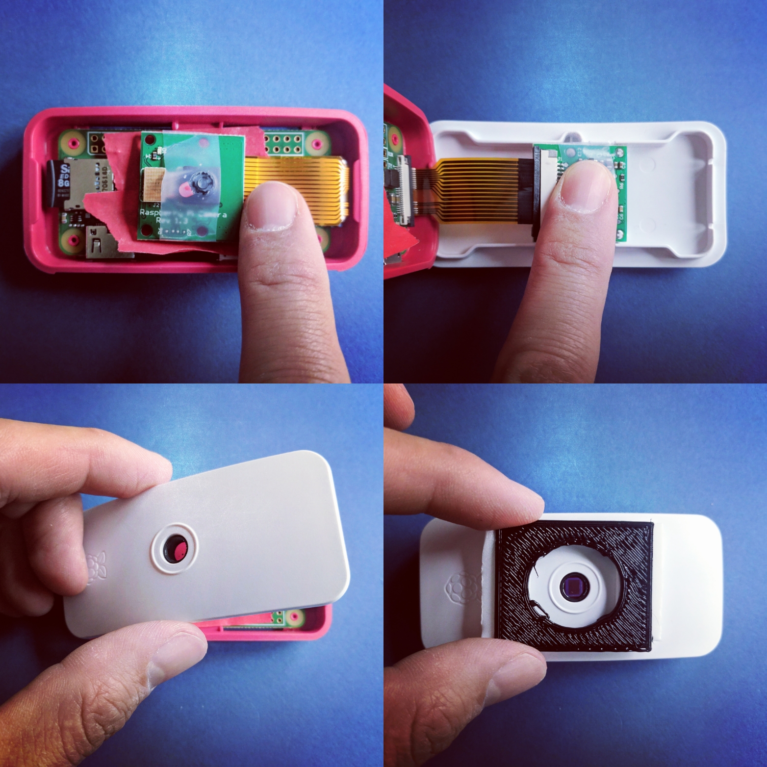
Step 3: CAREFULLY insert the cable exactly as shown. Orientation matters! Very gently, pull the black bar so that is loose (making sure not to separate it from the unit). Insert the cable so that it is firmly and evenly in place, and then push the black piece back in to secure it in place.
If you accidentally break off the black plastic piece (this piece is quite delicate), you can still insert it as you normally would, using a little bit of tape to help secure it (making sure not to cover any of the electronic components).
:
Step 4: Insert the wide end of the cable into the camera. There is scotch tape covering the lens to keep it clean during shipment and assembly.

Step 5: Place the board into the case as shown. The slots for the power and data ports will show you the correct orientation. There are spacers to ensure that the board is level and secure inside the case: if there is a lot of wiggle room, or if the board seems crooked you may have failed to align with the spacers.

The camera will rest inside the board.

Step 6: Fit the lens into the top piece of the camera case.

- and then close the unit.

Step 7: Center the lens adaptor over the camera opening, and secure it to the camera case using foam tape. Some users like to mask the sides with gaff or electrical tape to lessen the possibility of light leaks, but this is optional.
For the next step, there are 3D-printable adapter parts that are more complex and help change the distances and spacing more precisely than our adapter. (Ours was also 3d printed, although it's super simple) You can find a number of options at the OpenFlexure Microscope project.)

Step 8: GENTLY screw the lens into the adaptor. You may wish to separate the lens from the camera body if you are planning to travel with the microscope and think it may be jostled in transit.

Step 9:
Place your camera and lens on your camera stage so that the lens is centered under the top hole, as seen here, and then connect to power via the micro USB port on the side (the power and data ports are side by side, you don't need to use the data port unless you are flashing your own SD card--- the store kits come pre-flashed. 
Step 10: Connecting!
Once you assemble and plug in your Pi with the provided SD card (or flash your own from one of the recipes here):
- wait 3-5 minutes for it to start up
- connect to the
00-PiCamerawifi network with passwordpubliclab - wait for the popup prompt, or use
Click to log in to this network, or if nothing happens, go to http://pi.local(NOThttps, sorry!) and you'll see the welcome page.
Any questions/problems/suggestions? Post below and let us know!
4 Comments
A troubleshooting note!
The ribbon cables seem to be the most common thing to go wrong. Often, the "pad" next to the lens, shown here, needs to be pressed down again -- and beware that it doesn't get unstuck when you snap it into the Pi cover! I've sometimes just firmly taped it in place instead of snapping it in because there's so little clearance.
Second, the ribbon cables themselves are easy to get upside down. Look carefully at step 4 to see that they're in the correct orientation -- metal bits facing the circuit boards at both ends -- and that they are all the way in and tightened. See this photo:
Reply to this comment...
Log in to comment
Hi everyone- one minor (but very important) step we left out (now corrected). The Raspberry Pi needs to be plugged in to a power source to work! There is no internal battery-- there are side by side power and data ports on the side of the unit: you won't need to use the data port for anything unless you plan to flash your own SD card (the cards we ship with the kit are pre-flashed).
Reply to this comment...
Log in to comment
Hello,
A few questions if I may...
1) In your "make sure you have the camera parts shown below" photo, several pieces of read tape are shown. What kind of tape is this, 2-way?, masking?, electrical?
2) What is the purpose of the tape in 1) above? To keep the camera board isolated in some way from the raspberry pi board?
3) It is still unclear to me from the pics what should be done with the tape that has been put around the lens to keep it dust free. From the photos, it appears that the tape is NOT removed when putting the cover on the camera. What needs to happen for this step?
Once I get past these points, I can move onto worrying about whether I have the pi board connected correctly to the camera etc.
Thanks in advance,
Darren
Is this a question? Click here to post it to the Questions page.
Reply to this comment...
Log in to comment
Hi, Darren - thanks, great questions!
1 & 2. any tape should do - it is to avoid any possibility of electrical contact, yes. Sorry, should have mentioned it! But given the option, some kind of plastic (insulating) tape would be appropriate. This was just some red masking tape.
2) The dust protecting tape can be removed as the last step before snapping it into the case cover and closing the Pi case. I just hate the idea of dust getting in there, as I can't think of a good way to clean it off -- compressed air? So I left it on until the last possible moment. Think of the first Mars probe photo 😃 🤖 📸
Thank you too, and we'd love to see pics of your build! 🎉 🛠
Is this a question? Click here to post it to the Questions page.
Reply to this comment...
Log in to comment
Login to comment.