We are working to develop low cost spectrometers for UV-vis-near IR wavelengths based on the Toshiba TCD1304 charge coupled device. This is an update on our earlier work, which can be found here and here and here. It has been quite a while since we wrote about this and we have made and tested quite a few prototypes. In this research note, I am presenting some of our work on this effort.
Housings for some early prototypes were made from medium density fiberboard (mdf), plywood and foam insulation. Once we settled on an optical geometery, we began 3D printing the housings out of PLA. Optical components were mounted in 3D printed mounts and secured with either M3 machine screws or #4 sheet metal screws. We chose a crossed Czerny Turner optical geometry, as shown in the figure below. In this figure, light enters via the slit at the bottom, travels vertically to the collimating mirror, is reflected to the grating, then to the focusing mirror and on to the detector.

Early prototypes employed optical slits milled using a low cost CNC
router but we later switched to having them manufactured overseas. While we were able to achieve slit widths of ~0.2 mm using the router, our goal for this project is to offer a kit with the necessary optical and electronic components and the router method is not suitable for high volume production. Looking on Alibaba.com, I was able to connect with Donguan Electronics Company that made me 100 stainless steel pieces with the design below for a few bucks each. The slit width is 0.15 mm.

Our initial prototypes employed concave mirrors and gratings purchased from either Thor Labs or Edmund Optics. If you have ever looked into this stuff, you know these things are not cheap. Once we decided on the optical components, however, we were able to get a substantial discount from overseas vendors by purchasing in bulk. The photo below shows one of our more recent designs. In the back, you can see a 20 mm x 50 mm concave mirror we had manufactured for this project. The CCD detector is on a small circuit board that has wires connecting it to the microcontroller board in the foreground.

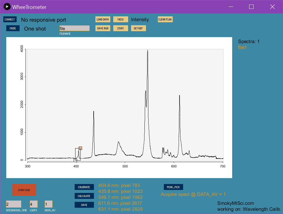
We tested the response of our prototypes by measuring the output from a compact fluorescent lamp (CFL). The results can be seen in the main image for this research note. We have made some good progress on writing the firmware and user interface. The user interface has a built-in wavelength calibration method based on the known CFL emission wavelengths. I put a demo of the calibration method on YouTube. You can watch it here.
Guess that is about all the typing I feel like doing. Let me know if you have questions.
2 Comments
That looks great! Can you reveal some details about the optics? Groove-density, focal lengths etc?
Is this a question? Click here to post it to the Questions page.
Hi Esben, Thanks for the comment, and thank you for your early work on the TCD1304. That was instrumental in us getting this project as far as we have. I apologize for not responding. I do not know why I did not see this until now. There was probably a notification but it must have been removed by a spam filter. The groove density is 1200 lines / mm, the collimating lense is 20 mm round with a 100 mm focal length. The focusing lens is rectangular, 20 mm x 50 mm. I plan to sell the optics and electronics from my website (SmokyMtSci.com). Right now, I am working on a version of the spectrometer based on the Teensy microcontroller board. Once I have the firmware and user interface finalized, I will put everything on GitHub and make a bunch of youTube videos demonstrating how to build one of these. I am working on getting information on this project up on my website. Best regards, Jack
Reply to this comment...
Log in to comment
Login to comment.