What I want to do
I'm trying to come up with a single-board prototype for Public Lab's Thermal Flashlight project. I'm trying to build on the great design ideas put forth in recent research notes -- the idea of adding a thermal flashlight shield to a Visuallight board, and the proposal to mash up the Sparkfun IR breakout board with a 32u4 processorand an RGB Led. I'm still rather new to designing boards, but I was inspired to do this mashup when I found Rui Wang's open source wearable computing project, which places an RGB, two rechargeable battery options (coin battery, or lipo via JST connector), and a piezo buzzer ('geiger counter' indications of temperature, whee!) all on a beautiful little board. Rui also added a light sensor, an ambient temperature sensor, a button, and has some nice large pin holes for attaching conductive thread. Those might be great things to include here, too, but I figured I'd drop them for now, for simplicity's sake.
My attempt and results
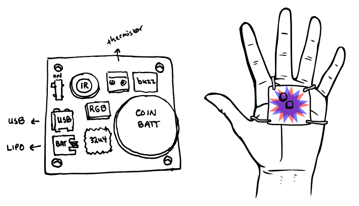
I've created a thermal flashlight board design github repo, where I'm working on an Eagle board. The basic layout idea was this:

Which, on the actual board, came out looking like this:

I've added four holes on the corners of the board -- I'm imagining that it can thus be attached to the end of a stick or cardboard tube, so that it feels like a 'flashlight' -- but then it occurred to me that it'd make a pretty cool "Iron Man"-style device, too:

Thermal fishing bob tie-in. I also figured that I should add a screw terminal to the board to allow for connecting a thermistor probe -- that way the same board could serve as a thermal fishing bob prototype (imagined here as simply sitting inside the translucent plastic 'powdered lemonade' container design, pioneered by Sara and Catherine):

Questions and next steps
Further work on layout and schematic. The design isn't finished yet -- still need to figure out the layout on the board, and I'm thinking that it might be a good idea to put breakout pins for a through-hole RGB LED for the thermal fishing bob case -- so that the LED could be bent at an angle and displaced away from the board, and would be more of a 'beacon' -- rather than being placed in the middle of the board. Also note: for the thermal fishing bob case, we could just opt not to place the IR sensor on the board, to make the design less expensive.
NOTE: in the github repo, the "32u4" design (which I think is where we should head) is the set of schematics / board designs that have "32u4" somewhere in the label.
Kit options. All of the board components are surface mount, except for the IR sensor and the screw terminal. So a good plan might be: have the board produced with only the surface mount components; then, when distributing a kit, include that board + a coin battery, and then additionally include a) the IR sensor, for a 'thermal flashlight' kit, or b) the screw terminal + a thermistor, for the 'thermal fishing bob' kit. Most folks could likely handle soldering those parts on themselves.
Anyone who knows something about Eagle design -- please feel free to download and tweak the board design and play around with the layout!
Why I'm interested
Seems like a single-sided, all-in-one thermal flashlight design would simplify production and reduce costs ... so here's my attempt at that ...
8 Comments
Wow, Don - fantastic and super speedy work!
One reason I was interested in the Visualight board was the strength of the LEDs -- really super bright! Take a look at their LED subboard -- could we integrate that kind of high-power stuff on this variant?
Is this a question? Click here to post it to the Questions page.
Reply to this comment...
Log in to comment
Also, did you do those completely rad illustrations?
Is this a question? Click here to post it to the Questions page.
Reply to this comment...
Log in to comment
Jeff -- ah, I see -- good point! I don't think I'm finding the proper Visualight schematic ... file:///home/chronos/user/Downloads/strip_02-schematic.pdf -- do you happen to have a link to the files / bill of materials / etc for their subboard? or the voltage required to drive the LED? I think we could just use a boost or buck converter on a lower / higher voltage battery to get the desired voltage -- I haven't designed this sort of power circuitry before, but Rui's a great local guru I can consult ...
Glad you like my illustrations! (I totally cheated on the hand bit with some clipart from the web, though :))
Is this a question? Click here to post it to the Questions page.
Reply to this comment...
Log in to comment
Awesome! This is what I was hoping to see and then some. I don't think I've ever seen something go from brainstorm to schematic so quickly! I was trying to make a mash-up between the Visualight Schematics and the Sparkfun Eval board on Fritzing. Unfortunately, I couldn't find a Fritzing part for the full Sparkfun MLX90614 Evaluation Board and I'm still learning how to create new parts. Its nice to see somebody using Upverter.com too! How did you find it? I've been hoping for a "Github for Hardware" for years and Upverter seems to be the closest so far. The problem for me has been its emphasis on PCB fabrication and schematics which requires a certain specialized skillset for which I have much to learn. Now that the Thermal Flashlight mashup seems to be well on its way, I'm thinking of incorporating the reference design into another project based on Public Lab research- A High-Power Red-Blue LED Grow-light configured to respond to visual plant health data collected through an IR-Camera. Is it OK if I base some of the baseline sketches off of your thermal flashlight repo? Having used Upverter, is this something you would recommend as well?
Is this a question? Click here to post it to the Questions page.
Reply to this comment...
Log in to comment
Woohoo! Quick replies / queries:
Is this a question? Click here to post it to the Questions page.
Reply to this comment...
Log in to comment
Do you have a link to the Visualight schematics? I should check them out, as Jeff was hoping to use their more powerful LED, and we might be able to incorporate that onto this board ...I was just going to use one of the files from the Visualight Github page- https://github.com/lpercifield/visualight/tree/rcgreen/Hardware. But I haven't managed to get that far yet. Is there not a usable schematic in that repo?
The "Github for Hardware" (nice way of putting that!) is something that so many folks I've met have been interested in ... farmhack.net had something like that in their tools wiki ... and Upverter seems cool ... but one issue it seems is that there are so many design tools out there, and so many file formats -- and so many ideas for what would constitute a 'design' -- that it's hard to accomodate all of that in one platform. Frankly, I'm finding publiclab.org's research note + wiki approach to be a pretty good solution, in this regard -- it's a flexible and fast way of putting up notes around a design ... witnessed in this note and its comments! :) But it's great to think about what the ideal solution would be (and build it / or incorporate it into the publiclab.org platform) ...I recently came to the conclusion that the, in the end, the "Github for Hardware" may in fact best be achieved by using...well...Github for Hardware. So I tend to agree with your conclusion. Unless you can convince everyone to agree on a common platform from the beginning, its probably best to emphasize flexibility and compatibility in a format. Despite its heavy developer-jargon orientation, Github continues to offer the most flexibility from my POV. The major weakness is in the wiki feature which remains buried underneath the main repo page. So I agree that the present research note format might be the best way to do it. I imagine it helps that comments are written in markdown too even if it requires me to brush up on my html.
Idea: Rui's Squarewear design uses a bootloader he wrote that allows one to use the Arduino IDE on an Atmega328 without requiring an additional chip to handle USB. This means that one could conceivably use a through-hole Atmega328p, a through-hole RGB LED, and a through-hole coin cell holder ... basically, I think the entire design could be a through-hole, easy to solder kit. Would that be a good idea? Or do we think it's more important to be able to assemble a lot of these easily (a surface mount design would be better in that case) ....This is a tough one... I can see as many merits in such an approach as drawbacks. Concerning the "through-hole vs surface mount" question I could see a lot of space between the flexibility of a breadboard and the permanence of a PCB. For example, I just noticed Adafruit is selling something called a "Perma-Prota Breadboard PCB"- http://www.adafruit.com/products/1608 that could fill this gray area to a degree. This could be especially useful for working with LEDs as it allows you to arrange them in any form. However, once you start getting into High-Power LEDs like the Cree XLamps, I'd probably be less inclined to trust my own ability to wire it safely.
The other question in my mind is whether or not it would be worth continuing with an ATmega328 even if it does have the ability to handle USB. Again, I see as many merits as drawbacks in the 328 for which I outlined a few in the comment thread on this research note- http://publiclab.org/notes/code4maine/01-22-2014/thermal-flashlight-using-mlx90614-ir-evaluation-board-from-sparkfun If one were to go with a through-hole soldering kit, the 328 seems to be a better choice, as in my experience the 328 has been much easier to program then the 32u4. On the other hand... a 328 might not be able to take advantage of some of the latest advances in cloud-sensor communications. The decisions of the Arduino manufacturers themselves might be a good indication of how these advances are unfolding. Not only has almost every new Arduino release since the Leonardo has been based on the 32u4, but when you look at their approach to the new Arduino "Yun" to their plans for the Beaglebone-like Arduino "Tre" to recent efforts towards making a web-based IDE, its not too difficult to see them moving in a more software-oriented direction. I don't think it would be a stretch to see the move from the 328 to the 32u4 as a first step in this direction. So my oversimplified formula is that people from an electrical engineering background prefer the Arduino Uno while software developers tend to prefer the Leonardo. My decidedly indecisive position on the merits of each approach is based in the fact that I am neither an expert in hardware or software...
Is this a question? Click here to post it to the Questions page.
Reply to this comment...
Log in to comment
Hi! Sorry for the delayed reply -- been a bit crazy with other projects, but still excited about this!
On reflection, rather than add extra power circuitry for a more powerful LED, I'm thinking that it might make sense to just add a few extra LEDs in parallel on the same board. I can add a few to the design, and then we can see whether the board is bright enough under typical conditions ...
Great thoughts re: "github for hardware" ... it's definitely a needed thing ... and maybe we're helping to build it out / prototype it here!
Very cool find re: the Perma-Prota Breadboard PCB ... will check that out ...
Re: the 328 vs the 32u4 -- good thoughts there, too. So, several options:
I think the only advantages of 1) and 2) over 3) is the 'through-hole kit' aspect -- even 2) isn't much cheaper than 3).
So, if we'd like to do through hole + simple, 2) might be a good way to go. The downside is that you can't use the usual Arduino serial monitor with the board -- need to find another way to get serial off the board (Processing, a Python script ...)
If surface mount is okay / preferable, then 32u4.
Interesting discussion re: cloud-sensor communications ... will have to look into that aspect of these design choices ...
I'll try to add some extra LEDs to the above design next week ...
The Cree XLamps are supercool -- are you planning on using them in your grow-light setup?
Cheers.
Is this a question? Click here to post it to the Questions page.
Reply to this comment...
Log in to comment
RE- Through hole kits- Interestingly enough... It appears we're not the only one's talking about an ATmega32u4-based breakout as this Kickstarter campaign is currently in progress- https://www.kickstarter.com/projects/myownduino/the-lil-nardo
RE-Cree XLamps- I just got my Visualight w/LED module and I can confirm its bright enough to hurt your eyes if you're not careful! Amazing how they get so much light out of such a tiny little diode! I now have little doubt that a string of XLamps, preferably mounted onto a flexible strip will provide enough light for an indoor plant set-up! As for the specifics of wiring them up, and how to program the Blue/Red outputs for each specific plants' needs, I'm working on a research note over on http://farmhack.net/wiki/open-source-pink-gardening-using-redblue-leds-indoor-plant-growth.
RE- Cloud-sensor comms... I don't want to get too carried away, but this issue may deserve its on research note on this forum as it is clearly one with enormous potential. There's a fellow I met at the Open Source Hardware Conference with an interesting system he calls "APITRONICS" (http://apitronics.com/) and I think he's on www.farmhack.net as well. His system uses a Beaglebone Black as a base station with the wireless nodes connected via XBees. This would've been almost exactly the same approach I would've taken until recently. The major game changer in my view is the new Arduino Yun, which merges a 32u4 with an Atheros chip running a modified version of Linux-OpenWRT. The same chip is used on the TP-Link WL703n travel router, prized by hackers as a cheap means of adding wifi to an arduino when flashed with OpenWRT. The Yun merges the router and the 32u4 on one board while communicating through a new "Bridge" library.
My idea is to find a way to use the same Atheros chip to control a network of multiple 32u4s OR to enable 1 or 2 Leonardos to perform multiple tasks simultaneously. As the Yun has a Leonardo chip embedded already, one would have to separate the components again, while retaining the "Bridge" library protocol. The TP-Link routers are obviously not designed for such a purpose, and lack sufficient memory to handle such tasks. There is a standalone development kit with the Atheros chip called "Dragino" (http://www.dragino.com/) that even supports the Arduino Yun firmware. So this will be my starting point for the time being. Unfortunately, the Dragino isn't widely available so I could see great potential for a dedicated Atheros AR9331/OpenWRT breakout that is specifically optimized for the recent crop of dedicated 32u4-based sensors (e.g the Visualight, the LeoPhi, LeoEC, "lil nardo")... Namely, it would require multiple USB/serial I/O ports and the capability of working as an XBee base-station with minimal configuration.
Reply to this comment...
Log in to comment
Login to comment.