
I measured angle g for multiple distances (D) between the entrance slit and the grating.
I made a few measurements on the SpectroBench 2000 of the best angle for the grating if it is made from a piece of DVD+R. I am not sure if most people are using DVD-R or DVD+R. Let me know if I should repeat these measurements with DVD-R.
With the entrance slit about 0.2 mm wide, I varied the distance (D) between the slit and the grating between 7.8 and 25.5 cm. I rotated the grating until the spectrum appeared sharpest to my unaided eye and measured the angle of the grating (g). I took measurements with the piece of DVD in two orientations: Either the outer, lower surface of the DVD was toward the slit, or the inner surface (exposed when delaminating the DVD) was toward the slit.
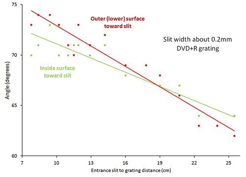 If the slit-to-grating distance is less than 15 cm, the sharpest diffraction pattern is formed when the DVD grating is angled between 70 and 75 degrees (angle g). The angle is the same regardless of which side of the DVD is facing the slit.
The result is similar to when the grating is a piece of 1000 lines/mm film, but the DVD+R grating must be rotated at a slightly steeper angle. When the slit-to-grating distance is less than 15 cm, the best angle is between 70 and 75°. There is no difference in best angle between the two orientations of the DVD. However, the curvature of the lines does seem to make a difference to the size of the spectral image. When the angled light approaches the DVD surface from the concave side of the lines the diffraction pattern is taller.
I did not measure the offset of the viewing angle from normal to the grating because I am not sure this affects the sharpness of a photographic image. But in order to center the visible spectrum in a photographic image, the camera would have to point 10° or 15° from perpendicular to the grating. If the near infrared spectrum is also being photographed, pointing the camera normal to the grating would probably work well.
21 Comments
What you are observing here may be related to what is referred to as the "blaze" angle of the grating. For actual diffraction gratings, the individual peaks and troughs my not look like a simple profile of horizontal and vertical lines. Instead the profile is more like a series of trapezoids. By adjusting these angles grating manufacturers can tailor the optimum order and wavelength for the grating. Given that information it is not surprising that there is an optimum angle of incidence for any particular grating. Now the question that still puzzles me is; why does the optimum angle change with distance to the slit? As I alluded to in a post on another of cfastie's research notes, this may be because of the fact that the light from the slit still has an appreciable divergence angle when it reaches the grating, and that begs the question, is the optimum grating angle dependent on the wavelength at which you are measuring the resolution of the system?
Is this a question? Click here to post it to the Questions page.
Reply to this comment...
Log in to comment
I am glad you raised the question of how the distance to the slit could affect how much the light was bent when it hit the diffraction grating. This would probably be a great high school physics puzzle in the hands of a capable teacher. Which I am not because my first instinct was to conclude that the photons must be aware of how far they have come from the slit. Photons must be able to remember stuff! So the first lesson is that diffraction is a phenomenon of waves, not particles. I suspect that you are correct that the absence of a collimating element is allowing waves from multiple directions to arrive at the grating and have some influence on this effect. My technique for determining maximum sharpness is to view the same two terbium lines in the CFL spectrum, so I am keeping wavelength constant in the process. Still inscrutable.
Reply to this comment...
Log in to comment
oh yeah, Love the lego optical bench and the discussion in the other research note.
stu
Reply to this comment...
Log in to comment
well done cfastie, thanks for taking the time to conduct some measurements. I've been pondering over the pattern and the angles for some time now. (see related postrs in the PLOTS-spectrometry list).
I'd like to add a few things to this, hopefully shedding some light from a High School physics teacher's perspective ! Sorry if some of it is dumbed down a bit, I'm writing for the whole audience.
Firstly, the "collimating slit" is purely to create a source that is in phase. The light (photons or waves, it matters not, there are ways to mathematically show the same effect either way) must be coherent. A jumble of incoherent waves hitting the DVD, since they have a random phase relationship, won't produce any pattern. There are two ways to achieve this, one is to look at a pinpoint light source from a great enough distance, the other is to create such a source by passing the light from a non-point source through a narrow aperture. Huygen's principle. There are formulas for working this stuff out and it is related to the distance a human eye can resolve car headlights as being a pair rather than a single source. The resolvable limit of two points close to each other each emitting light.
The link is a good discussion, from a high school level about different diffraction gratings.
http://spiff.rit.edu/classes/phys213/lectures/grating/grating_long.html
as an aside, I confess to being a bit mystified by the pattern when you use the new DVD by itself to look at flouro or incandecent halogen lights to get the nice reflective rainbow. The sources are incoherent, but the reflection diffraction grating interference pattern is striking and not affected by the need for collimation nor by the size of the source. If anyone has an explanation, I'd be grateful !
anywho, in the transmission diffraction grating (as opposed to the reflective type) the wider the collimation slit that is used, the more light we get but the less fine the final interference pattern. I think this is because the wide aperture just shines a beam of light onto the grating, whereas a small aperture causes divergence of the beam onto a wider slice of the DVD grating and the more grooves that are illuminated, the better the resolution. The light that is incident on the DVD must still be coherent.
Looking at this and the possibility of a small divergence from a slit used to let light into the apparatus, I could imagine the further away the grating is placed from the aperture, the more grooves are illuminated and the better resolution that can be achieved, also altering the geometry slightly. This might be an explanation for the changing precision and need to re-angle the camera as the slit to grating distance is changed, but it is only a guess.
But the distance of the collimation slit to the grating shouldn't matter otherwise. The light from the single slit is simply being spread out (like waves through a narrow opening), the narrower the opening, the better the semicircular wavefronts on the far side (and the less the side effects which produce single slit interference). In our case, the opening is very wide in comparison to the wavelength of light, so a sizeable chunk of "straight" wavefront is allowed through and this is what the camera is focussing on after it has been diverged by the grating.
I suspect that the small changes in angle you observed are caused by very small changes in the angular alignment of the camera and DVD grating as you alter the distance. Your results show that doubling the distance involves an angle change of only 5 degrees or so. It must be very hard to keep everything lined up while you shift the opening and moving the opening side to side changes the geometry.
What is important are the two angles between the grating and the single slit and between the camera and the grating. Normally an interference pattern is observed by setting the grating at right angles to the source and viewing the pattern by projecting onto a screen (or eyeball). This is the form of the classic formula ml=d sin(theta) we use at school.
In the experimental setup we use, we place the camera sensor parallel with the grating and observe one side of the pattern, taking advantage of an asymmetry produced when an incident angle (angle between grating and slit) is introduced. This angle produces an asymmetric pattern, one one side we have:
sin(theta i) + sin(theta d1) = l/d
and on the other side we have
sin(theta i) - sin(theta d2) = l/d
where: theta i = incident angle of the light onto the DVD theta d = angles of observed maxima from the grating. l = wavelength of light d = diffraction grating spacing (note, I have deliberately changed the signs of theta d so that it is obvious one is an addition, the other is a difference, text books simply incorporate that sign into a convention for how the angle is measured)
I think we use the second side of the pattern. With a largish value for theta i, this produces spectral maxima that fall within the viewing area of the camera.
This asymmetry can be easily seen by shining a laser through the DVD grating and projecting the interference pattern onto a screen. If the DVD is at right angles to the laser beam, the two laser spots will be equidistant from the central maxima. As the DVD is angled, one spot increases its distance and the other gets closer to the central maxima.
In our setup, theta i is around 60 degrees, so we expect to see red on the screen at an angle of almost zero (say, in the centre of camera image) and blue at an angle of 20 degrees. The exact positions will be determined by the distance of the camera from the grating, increasing it will move blue off the screen (still at 20 degrees though) ! These are rough back of envelope calculations, so don't take them as gospel.
The blaze phenomena I think is related to reflection gratings, not to transmission gratings ? (probably a bad guess on my part !) . And then it is related to a particular design of grating.
stu
Is this a question? Click here to post it to the Questions page.
Reply to this comment...
Log in to comment
Stu, Thanks for the lesson! It’s really good to get a feeling for these concepts. I wish you had been my high school teacher. TomH sent me a spreadsheet with the grating equation that’s fun to play with. So I am getting an education from all sides. Maybe he should share that spreadsheet in a research note.
I tried your demonstrations with a laser and also looked at the diffraction pattern with the grating perpendicular to the light path from the slit. Although observing the angles of the right side and left side first-order spectra is informative, it seems relevant that I was not able to see a sharp image of the diffraction pattern by looking into the grating when it was perpendicular to the light path. Only when the grating was rotated to an angle between 40° and 65° was I able to see a sharp spectrum, although a blurry spectrum was always visible.
I have been puzzling about the absence in the grating equations of a variable for the distance between slit and grating. You must be correct that the distance should not matter, and the absence of that variable in all the standard equations confirms this. But the phenomenon I recorded appears to be real. At certain grating angles, it is not possible to see a sharp image of the spectrum when the grating is too close to the slit. But the same grating angle produces a sharp image when the distance to the slit is increased. I am not using a camera to observe this, just my eye. This must be an artifact of some feature of the setup. I suspect the artifact might apply to all of these setups with no collimating optics. Maybe someone else can try to repeat my results.
That’s a good observation that holding a grating up to a CFL bulb produces multiple overlapping images of the bulb in different colors (corresponding to the colors of the main peaks). This seems to argue against the requirement that the light be coherent to produce a diffraction pattern. But I’m not sure what that really means.
Chris
Reply to this comment...
Log in to comment
I think the reason that Chris has trouble getting good resolution at certain angles has to do with the eye's focusing mechanism, and the focus may be getting out of range, or other things in the field of view may be influencing the eye focus.
Now I think I understand some other observations that have been reported in the PLOTS spectroscopy forums. People have focused their webcams at distance x, and set the slit at x only to find that the best spectral image is obtained with the webcam focused at distance y. Here is what I believe is the explanation: 1)Remember that we are working without collimating lenses and relatively short slit to camera distance, therefore the light has a significant amount of divergence when it reaches the grating and then the lens. 2) That amount of divergence is changed by the grating according to the grating equation, and inspection of the equation would lead one to believe that the relationship is non-linear. 3) With the grating angle at o° (i.e. plane of grating normal to the direction to the slit), if the incidence angle changes by 1°, the diffraction angle will change by 1.47° for the dvd 1350 lines/mm spacing at 550 nm light (about the middle of the visible spectrum). 4) Therefore light from the slit after diffraction is diverging more than before diffraction, and more divergence is like having a closer object to camera distance. 5) I verified this in a semi-quantitative way by using a webcam with adjustable focus. In one experiment I had the dvd piece set up normal to the light (incidence angle = 0) and the webcam had to be at about 45° in order to capture the spectrum. The grating was 29.5 cm from the slit and the webcam 0.5 cm behind that. I used a slider in the webcam controller to obtain best focus. After I had done my spectral measurements I did some focusing experiments and found that, for the webcam to focus on an object at the same slider position, the distance was now 15 cm. So, after the light from the slit has been diffracted it is diverging as if the slit were only 15 cm instead of the actual 30 cm.
Now, when the angle of incidence is about 22°, the change in diffracted angle is about the same as the change in incidence angle, and beyond 22° the change in diffraction angle is less than the change in incidence angle. So beyond 22° the webcam should be focused at a point beyond the slit distance. This explains an observation I made earlier; I did not need to focus the webcam for close distance using the setup described on the PLOTS website for the spectrometer housed in the VHS box.
Incidentally, the focusing webcam I referred to above is a Logitech 9000, and it has a 1600x1200 pixel array.
Reply to this comment...
Log in to comment
Chris, you said:
"At certain grating angles, it is not possible to see a sharp image of the spectrum when the grating is too close to the slit. But the same grating angle produces a sharp image when the distance to the slit is increased."
maybe, just maybe, you've gone inside the distance where the slit acts as a coherent source ? I'd be very happy to hear this, for it puts me on more stable ground ! I want coherency before I want to see interference patterns !
Tom, excellent discussion, thanks. I'm realising the geometry of the slit to grating is really important. In the double slit experiment, the diagram in every text book shows the single slit which illuminates the double slits, makes a perfect wave, where complete diffraction has taken place and beautiful semi--circular wavefronts are produced. The double slits are illuminated with waves that have travelled the same distance and which are also in phase, having originated from the same idealised point. (They don't actually have to travel the same distance and so arrive in the exact same phase, but whatever phase relationship they have as they hit the double slits must be constant.)
Our situation is different. The slit isn't small enough to produce the nice clean 180 degree dispersed semi-circular pattern favoured by text books and we have a bright (as you point out) slightly divergent beam. So when this falls on a linear grating, the divergence is creating a path difference (or creating a variable incident angle change, as you suggest) and this affects the pattern.
The key to the fineness of the lines, that we teach to our students, is that it is only at a specific angle (path difference) that multiple adjacent slits all reinforce constructively. At any other angle in between, while adjacent slits might partially interfere constructively, there is a slit so many places away (say 1000) that is half a wavelength out, which exactly cancels the first slit. The second slit is cancelled by the 1001 slit, the third by the 1002 slit and so on. Illuminating more slits makes the line that is reinforced so much finer, at a very precise angle, due to this cancellation effect. Hence the difference between a double slit (varying intensity between peaks) and a grating (discrete peaks with almost no intensity between). Well, that is what we teach !
If we had a perfect (narrow, approaching the wavelength of the light) slit, the light would diffract the full 180 degrees and there would be no diverging beam, just a perfect pond like ripple. The part of that perfect wavefront that hits the grating would have negligible path length difference (except for that caused by the deliberately introduced incident angle). On the other hand, I think, a wide slit throwing out a beam would have a path length difference from one side of the beam to the other (and there would be less grating slits illuminated as well).
Chris said: "it seems relevant that I was not able to see a sharp image of the diffraction pattern by looking into the grating when it was perpendicular to the light path. Only when the grating was rotated to an angle between 40° and 65° was I able to see a sharp spectrum, although a blurry spectrum was always visible."
If the grating is not producing sharply defined lines then not enough grating is being illuminated, the phases of the waves as they are hitting the grating are not consistent (see above) or there is nothing bringing the rays back into focus, so they occupy the same beam width as the original beam that is illuminating the grating (focusing problem, see below). In each case the colours are not produced as a line, but as a smear and the whole spectrum isn't well defined. Maybe when the grating is angled, the angle is correcting the phase differences of the incident light due to the nature of the beam we are using ? As Tom says, the incident path difference being "cancelled" by the diffracted path difference introduces some fine tolerances. I notice with my laser and the DVD, when angled, one side is sharp, the other side is smeared.
But I've got to confess, this is just conjecture. I'm really out on a limb trying to reconcile perfect text book physics with optical reality. Likewise thinking about the focusing problem:
Tom said: "Now, when the angle of incidence is about 22°, the change in diffracted angle is about the same as the change in incidence angle, and beyond 22° the change in diffraction angle is less than the change in incidence angle. So beyond 22° the webcam should be focused at a point beyond the slit distance. This explains an observation I made earlier; I did not need to focus the webcam for close distance using the setup described on the PLOTS website for the spectrometer housed in the VHS box."
my understanding of focusing, somewhat simple I know, is that the image is in focus if all the light emitted from a point on the source is brought back to a single point on the image. If the source is a point or slit, then the camera should be focused on that point or slit. In our case, the light rays, as they leave the grating are, for a particular reinforced wavelength, parallel. So the camera or eyeball is essentially focusing parallel light rays, which look like they have originated from a point an infinite distance away.
In other words, the light source (slit) is a set 10cm away, but the green light rays from the grating, at a given angle for constructive interference, are actually parallel. (This is fudged in the school text books by saying the slit separation is small, the screen is far away and the rays come together). Better texts actually place a converging lens after the grating, as we are doing with the camera lens. So what we are perhaps seeing is the need to focus light rays that have been parallel by the grating in the focus distance of the camera. Which is very convenient for us actually, given the minimum focus depth of cheapy webcams !
dunno, this stuff is starting to keep me awake at night !
stu
Is this a question? Click here to post it to the Questions page.
Reply to this comment...
Log in to comment
Hi straylight, You make some good points, and I think you need to think more about a couple of things.
1) Even with a slit small enough to produce coherent light there will still be an angular difference from one point on the grating to another. Remember the ripple on the pond analogy? When those ripples intersect a plane surface different parts of the ripple will hit the plane surface at different times. So in the spectrometer there will be different path lengths and differing arrival times as well as different angles. With pencil and ruler draw a line from a point to a line representing the grating say 10 cm. away, now draw a line from the point to the same grating line but intercepting the line say 1 cm away from where the first line intercepts the the line representing the grating. The two angles of incidence are different. This is most readily apparent when one line from the point is perpendicular to the grating line.
2) Lets talk about the camera and focusing. Think of a point being imaged by a lens and the point is close. Light striking the lens from the point will have some divergence angle (think of the angle made by rays striking opposite sides of the lens or center of the lens versus the perimeter). Light coming from a point a more distant point will have a different divergence angle and therefore be imaged at a different distance from the lens. Remember the thin lens equation 1/f=1/i+1/o. The divergence angle is the ultimate reason for this. Again a pencil and paper help. You can do some simple ray tracing to show this. To do ray tracing you can let a line represent the thin lens. A ray striking the lens along the optical axis (in this case perpendicular to the line that represents the lens) will be deflected so that it crosses the focal point of the lens, and a line passing through the center of the lens will be undeviated. So with a line and some points on paper you can do some ray tracing.
I wish there were a simple way to upload images to this site, then I could easily send some drawings to illustrate my points.
Is this a question? Click here to post it to the Questions page.
Reply to this comment...
Log in to comment
Tom, images would be very helpful (so my mind doesn't explode). If you upload images to a site like Flickr or Picasa you can grab the HTML embedding code there and paste it into these comments or use the image tag ("Enable rich-text" first) to link to those sites. Or start a new research note which allows a gallery of images from your hard drive. Or make a post at the Google group which allows inserting photos from your hard drive.
Reply to this comment...
Log in to comment
Chris, I will work on doing an upload somehow. I have plots-spectrometry in my google groups, but I can't find these research notes there.
Reply to this comment...
Log in to comment
The Google group is completely separate from this web site, so the two places have somewhat independent conversations. I guess the Google group is seen by more people, so the feedback can be better there.
Research notes are a good way to share things with rich media and they are fairly easy to find later on. The Google group might be a better place to have conversations, mostly because more people might participate.
Reply to this comment...
Log in to comment
Your text to link...O.K. I am going to try to insert drawings from Picasa:
it seems I haven't learned to do imbedding, but here is the link https://picasaweb.google.com/115538024473775757519/Spectroscopy#5847102038524821346
Reply to this comment...
Log in to comment
maybe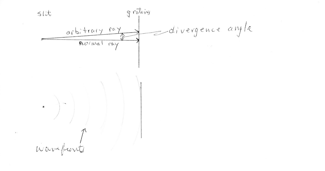 I have it now
Reply to this comment...
Log in to comment
Well done,Tom.
This article which was mentioned at the Google group, discusses the issue of focusing on the spectral image. It even has an equation with a variable for the slit-to-grating distance. All of our questions are not answered, at least, not very clearly, but some of them are asked. Maybe someone can explain to me what the authors think they are saying. I'm not sure everyone will be able to access the full article.
Is this a question? Click here to post it to the Questions page.
Reply to this comment...
Log in to comment
I was able to get a copy of the article. From a brief scan it looks very pertinent to what we are doing/discussing, but I have not really read it yet. I have to attend to some other things besides this :-)
Reply to this comment...
Log in to comment
I don't know if this will clarify anything, but I'm finding using a laser beam from a red laser pointer quite useful in examining what goes on with these gratings. Since it provides quite a coherent beam of light it eliminates the question of beam spread from a slit. Of course the laser must be observed by relflecting it off a 'screen' surface. It's not a good idea to be pointing it into a camera or an eyeball.
I have samples of 500 lpmm and 1000 lpmm holographic film and of course pieces of a split DVD-R. The laser approach is used in a presentation available on the internet from schools and the Georgia Institute of Technology, where they measure the dispersion angles for CD and DVD. The track pitch of a 4.7GB DVD-R is 0.74 microns which gives a line spacing of 1,351 lpmm (CD is 625 lpmm) and the GIT experiments showed that firing a laser beam through with the CD and DVD at right angles to the beam showed a diffracted dot on either side of the main beam at 25.3 degrees for the CD and at the quite extreme angle of 64.8 degrees for the DVD. I have roughly repeated their experiment and these angles seem about right. Twisting the grating away from normal appears to spread the beam spot on one side and compresses it on the other. Spreading the beam a little would effectively allow higher definition spectra.
Comparing the CD and DVD material to the 500 and 1000 lpmm holographic film, the diffraction angles aren't as extreme, at 19 degrees for the 500 lpmm and 36 degrees for the 1,000 lpmm.
The diagram at the top of this thread is interesting because it shows the beam paths exactly as they would be for the laser angle measurement experiment. The difference is the direction is reversed. The camera is where the laser would be (it's appears to be only a little off being at a right angle to the grating) and the slit is where the diffraction angle observation would be made. Of course it doesn't make any difference to the light path which way round things are (I have checked with the laser and if you shine it at 36 degrees to the surface of the 1000 lpmm holo film, a dot appears on the other side showing a beam at right angles to the film). I think you would get much the same results if you set the grating at right angles to the beam from the slit and placed the camera at around 65 degrees, which would agree with the resuts of the diffraction angle measurement experiment.
With the tightly collimated beam from the laser it doesn't really make any difference what the distance between the laser pointer and the grating is. The two diffracted beams still appear at the same angle and beam spread on either side of the main beam.
BTW I think the difference in angles between the holographic film and the DVD are not just because the DVD has slightly tighter line spacing. There are apparently two profiles used for diffraction gratings - one with a sine wave like cross section (only perhaps sometimes with steeper verticals) and a sawtooth like cross section which is known as 'blazed' or echelette grating. Blazed gratings provide maximum efficiency at a particular wavelength determined by the blaze angle. The first comment in this thread speculates on the effect of blaze angle, but a CD-R or DVD-R most closely resembles the 'sine' type of grating, not a blazed grating. Most holographic gratings are sinusoidal. The large difference in diffraction angle between the DVD-R and the 1,000 lpmm holographic film will in part be due to the line spacing difference, but I think the groove depth is deeper for the DVD and that explains its rather extreme diffraction angle.
In the Public Lab kit design the wooden block angle is around 50 degrees and the slit is placed a little below the positon of the lens, so again the angle of around 65 for the DVD-R diffraction angle is met.
Reply to this comment...
Log in to comment
I'm making a simple spectrometer to extract the spectral response curves of an imaging sensor. To this end I made some calculations to help me designing the grating configuration. I thought this might be of use to some.
Using the equations as mentioned by straylight and here I put together a graph crossing incident angle and wavelength in function of diffraction angle (for different grating densities).
The results for a 300 lines/mm grating and a DVD 1351 lines/mm are listed below. I hope this helps in getting a feel of diffraction characteristics as discussed in the post. It clearly shows increasing non linearity across the spectrum with increasing number of lines. The middle of the spectrum (of interest) is marked with a vertical line. The horizontal line marks the angle at which the middle of the spectrum is orthogonal to the grating.
For those familiar with R ask me the script to generate these figures, markdown doesn't handle it inline very well.
Is this a question? Click here to post it to the Questions page.
Reply to this comment...
Log in to comment
thanks khufkens, interesting graph and really well presented.
On a qualitative level, you can see this by shining the red laser through a DVD grating and changing the incident angle slowly. At a certain incident angle, the addition side of the diffracted angle accelerates quickly off the screen while the subractive side (the side you have plotted) gets closer to orthogonal and at the point you have clearly identified, goes past orthogonal.
While the graphs show the non-linearity of the spectrum captured by the camera, it is important to see that the horizontal line in both graphs indicates the diffracted angle vs wavelength is actually close to linear. The spacing of the dashed lines at +20 degrees to -15 degrees is almost equal along the horizontal line, so the assumption that wavelength can be extrapolated accurately from diffraction angle (or position in image) is valid, as is borne out in practice. You have shown clearly that angling the grating to 65 degrees improves the linearity. At zero degrees of incidence, 380 to 480 nm is spread across 8 degrees, while 580 to 680, same 100nm range, is spread across 20 degrees. That would make calibration of our spectroscopes quite difficult.
Just to be clear, the actual reason we angle the grating and camera and introduce an incident angle is so that the spectrum that is produced falls neatly onto the camera with the grating stuck to the lens. We could do it without an incident angle by separating the grating from the camera and moving the camera around in an arc behind the grating until we find the position of the spectrum. But this would push us (down) into a non linear region as shown on the graphs above. So really it is a win-win, something I hadn't thought about before.
stu
Reply to this comment...
Log in to comment
Related, I found this post, discussing in part the asymmetry in the current desktop spectrometer design. I'm designing a symmetrical layout similar to what is discussed in the post. From a practical point of view the symmetrical design is far easier to implement.
Reply to this comment...
Log in to comment
Wow @khufkens, I think your graphs and notes merit a new research note... We could link it to this note as a followup?
Is this a question? Click here to post it to the Questions page.
Reply to this comment...
Log in to comment
@warren, not sure it justifies a separate page yet, my comment is rather low on details / text. I would need to put some context to it all if this has to stand on it's own. I'll see if I can carve out some time to write things up. This was all part of a blog post of mine, which is here, this might be enough to start a new note.
Reply to this comment...
Log in to comment
Login to comment.