What I want to do
This is a part of our bigger program in laboratory automation. We published an earlier research note (found here) that describes automating a valve that only has to turn about 90 degrees. In this research note, I describe our work on a more complex type of valve that I will eventually tie into an instrument for automating peptide synthesis. In this research note, we describe automating an eight port distribution valve. A distribution valve is a valve that has a center port that can be connected to any one of some specified number of outlet ports. By connecting a syringe pump (like the one we describe in this earlier research note) to the center port, we can withdraw a liquid from any of the outlet ports into the syringe and inject it into any of the other outlet ports. The ports all are threaded to allow connection of ptfe tubing using the appropriate connectors. In principle this should be very useful to automate a large number of laboratory tasks.
My attempt and results
This project uses some commercially available hardware, a bunch of 3D printed plastic parts, a little bit of electronic hardware, and some software. The thing that makes this project trickier than the one in our previous research note is that the valves have to rotate though a larger angle. Servo motors like the ones that we used earlier typically have accessible rotation angles of 90 or 180 degrees. For an 8 port distribution valve, we will need to be able to rotate the valve through at least 315 degrees (although a full 360 degree rotation is better). Another complicating factor is the fact that the 8 port valves are bigger than the valve we used earlier and require more torque to turn. To get around the issue of required torque while still maintaining a low budget, we decided to use modified servo motors to turn a larger gear that is attached to the valve. This configuration requires the servo be able to undergo continuous rotation, not the 90 or 180 degrees that they come as. Modifying the servo is pretty straight forward and is described in a bunch of you tube videos. Before you buy a servo for this, make sure it will be easy to modify. We used HiTec HS-425BB servos from ServoCity.com.
Servo modification:
To modify the servo, open up the back and take out the potentiometer that provides feedback control to the motor driver (there is a little screw holding it in). The figure below shows the pot.

This will be replaced with two resistors set up to be a voltage divider (shown in the figure below). I think we used two 5 K resistors.

Clip the ends off of the wires, then wrap everything with electrical tape making sure nothing is shorted out and stuff it back into the housing.
Once you have the electronics taken care of, take the front off of the servo so you can get at the gears. The figure below shows what the servo looks like with the end plate off.

One of the gears has a little tab on it that prevents the gear from turning completely around. In the figure below, I have marked the tab with a black pen to make it easier to see. You will need to remove the gears to get at it and cut this tab off using a utility knife.
 Once you have the tab cut off, you can reassemble the servo and it will be capable of continuous rotation.
Mechanicals
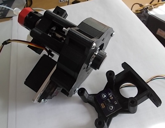
Some of the mechanical parts are in the figure below.

On the far left is the 8 position valve (Hamilton Company, HVXD8-5 VALVE, $172), then a 3D printed valve mount with a 1/4" to 1/4" shaft coupler (Servocity, 625104, $5) just above it. To the right of that is the servo, mounted to an aluminum plate (Servocity, standard plate C, $6), another printed plastic mount, and a dual ball bearing hub (Servocity Part: 545444, $7). To the right of the ball bearing hub is an aluminum hub gear (32 pitch, 72 teeth, Servocity, part 615198. $13) mounted on a 1/4" clampling hub (Servocity, part 545588, $8) and a 1/4" shaft. The aluminum hub gear is turned by a 24 tooth 32 pitch servo mount gear on the servo (Servocity, part 615286, $15, not shown).
The valve is attached to the printed plastic mount as shown below.
 The valve mount gets bolted to the rest of the assembly as shown. The order is; valve mount, standoff mount, servo plate, then gear housing. The figure shows the view from the bottom. Note that you can get to the set screws for the shaft coupler from this angle,
 The picture below shows the inside of the gear housing with bolts (#6 x 3" pan head machine screws) running up through it. It actually fits better if you run the bolts the other way, with the heads inside the housing.

After you have this assembled, the aluminum gear assembly (with the 1/4" shaft goes in as shown below (actually, we have started putting it in with the hub on the outside of the gear instead of on the inside as in the figure. This makes it easier to adjust the shaft position). Once the gear is in, you should be able to connect the shaft to the coupler by tightening the set screw on the other side of the assembly (two pictures up).

The next thing to go on is the magnet mount, which press fits onto the shaft.
 The magnet mount holds a 3/4" ceramic disk magnet that you can purchase at any hobby shop (the company that makes the magnetic sensor recommends much stronger magnets, but we were unable to get them to work). After pressing the magnet into the mount and attaching the cover plate, the valve assembly should look like the following figure:
 The part to the left of the valve assembly in the figure above holds the rotory position sensor. It should have been screwed to the cover plate before the cover was attached to the valve assembly, but this way you can see that the plastic part holds a little circuit board with an AS5600 rotary position sensor. The position sensor determines the direction of the field from the magnet that is mounted on the shaft. The circuit board just holds the chip in place and has one capacitor and three wire pads: the one on the left is for +3.3 volts, the one on the right is for ground and the one in the center outputs a voltage that is proportional to the measured angle. The mounting holes line up with holes in the the printed mount to hold the chip directly in line with the center of the magnet. Basically, this is a potentiometer that rotates 360 degrees and the rotor does not snap off when you twist it beyond it's limits.

The final product is shown below from the end with the magnetic sensor. Notice that the wires from the position sensor exit through the mount.
 The servo motor requires a 6 volt source. Since we plan to use these valves in coordination with with syringe pumps that run off of 12 volt DC, we are using a 12 volt "wall wart" with the voltage stepped down to 6 volts using an adjustable low dropout oscillator (LM317DCYR). The rotational position is read as a an analog voltage by a read pin on our microcontroller (LaunchPad Tiva C) and the microcontroller outputs a pwm signal to run the motor. Outputting different pwm values causes the motor to run slow or fast, either one way or the other.
Questions and next steps
The next step is to write up a note about the software.
Why I'm interested
Three of these things are going into an automated peptide synthesizer that I am making.
2 Comments
Wow, this is a gorgeous piece of equipment. It seems to represent a huge effort in design and construction.
I was pleased to learn that continuous rotation servos are now available for about the same price as standard servos. Pololu has a few for good prices: https://www.pololu.com/category/143/continuous-rotation-servos.
I hope the demand for peptide synthesis skyrockets and you corner the market.
Nice work,
Chris
Reply to this comment...
Log in to comment
Thanks Chris, I don't expect that anyone will be making much money off of open-source science stuff. I see this as more of a service to my discipline (lowering the cost of teaching so that more people can learn about solid phase synthesis). The design has been through a few rounds of prototyping so it's availability should save people a fair bit of time.
Thanks for bringing the pololu servo to my attention. I will check that out. Servocity will modify the servos that the sell, but the markup is a little high for it to be worth it to me. Thanks again, Jack
Reply to this comment...
Log in to comment
Login to comment.