What I want to do
Continue spare-time development of a smaller, more stable and compact, multi-use cuvette frame attachment for the 3.0 Desktop Spectrometry Kit, summarized in a few previous posts by myself and @tonyc:
- https://publiclab.org/n/12561
- https://publiclab.org/n/12462
- https://publiclab.org/n/11063
- https://publiclab.org/n/12472
My attempt and results
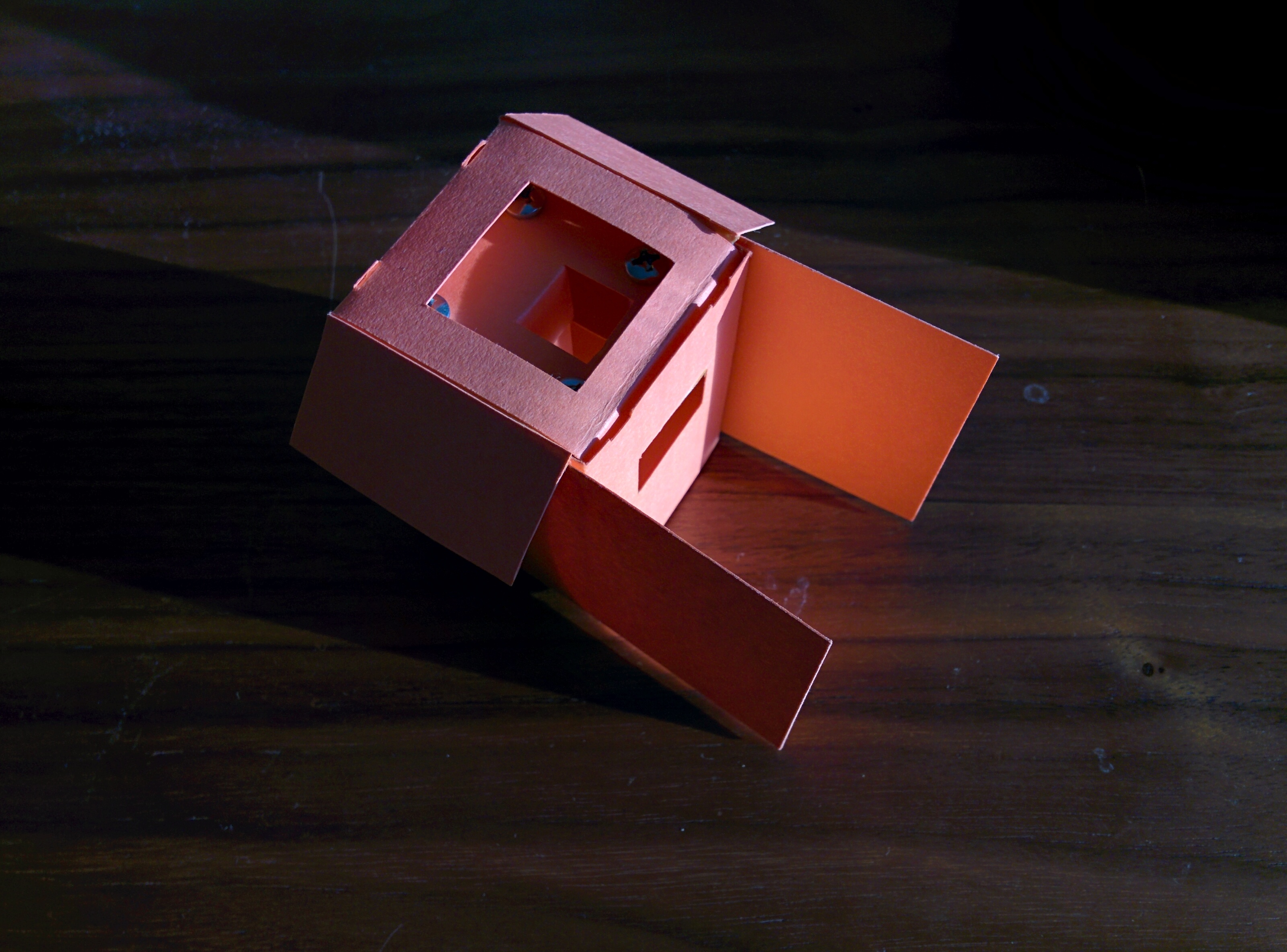
I developed a vector design for my Silhouette Cameo desktop paper cutter, trying to get it to fit on a letter-sized (8.5x11") sheet. I modified the design after printing and assembling it; see my modifications in the laid-out-flat photo below.


The internal part is made of two C-shaped folded pieces which bolt together using long bolts spaced out with 1/2" nylon tubes; one nice thing is that I believe the whole thing can be very precisely raised and lowered by turning the bolts; they hold on the cardstock. A final version might be made of a flexible plastic sheeting.
The two "wings" slot into the slots on the spectrometer, and index at all four corners. Because of the fold-over bottom and top, it's very sturdy. I put a hole on the back for where the knob for dimming the light will go -- remember, we're going to try to get this working with LEDs, and if not, maybe a laser diode component, dimmed with a dial.
The "stack" fits inside and is folded over with a big flap, like this:


Questions and next steps
I haven't added the extra flaps to the digital file yet, but they're pretty straightforward, and I'll update soon. And there are some sub-millimeter sizing issues on the "stack" -- and i also messed up one of the screw hole locations.
Then I'll need to try putting the electronics in. I'm going to try to screw the Arduino Trinket and the LED board directly to the paper enclosure.
Update: adjusted the digital file to match the modifications; still needs some work on sub-millimeter sizing and maybe flap locking: cuvette-frame-7.pdf (have to modify publiclab.org to accept dxf uploads)

9 Comments
Hey Warren, I downloaded the pdf cuvette frame design and I was wondering if I print it out will it be to scale so I can use it as a template?
Is this a question? Click here to post it to the Questions page.
Reply to this comment...
Log in to comment
I think it will be! But its designed to fit on the 3.0 spectrometry kit, and I think you have the 2.5, no?
Is this a question? Click here to post it to the Questions page.
Reply to this comment...
Log in to comment
That's ok, I'm going to try it out anyway. I think this will work for what I am thinking, I am going to mount it in a plastic utility enclosure and if this template works then after it's built I can make it a little more ridged by laquering it.
Reply to this comment...
Log in to comment
I tried cutting the new version and it worked pretty well:
I worked to insert the LED (which could be a laser diode) dial, and Trinket (arduino clone) into the enclosure.
Unfortunately, the "stack" hits the components when you insert it, so it had to be modified quite a bit. I think that a different design for the stack, which incorporates the mounting of the components, is probably the way to go. Then you'd insert the stack into the box, it'd be stable on its own, and the screw of the knob would still stick through the outer box before the cap went on.
Anyways I just cut the stack paper away to make room for all the parts, and used lab tape to stick things in. The USB port peeks out nicely:
I also added some tabs and slots to make it stay closed without tape. I want to work on the rest before recomposing a digital file, though.
Reply to this comment...
Log in to comment
Just notes to self; i want to:
Reply to this comment...
Log in to comment
That is just too cool Jeff!
Reply to this comment...
Log in to comment
Another update with the tuck-in flaps, slits, and the USB hole and the indexing hole for the potentiometer (although that may be premature). The design of the stack is going to be changed a lot, and the cuvette moved up against the window. The rest of the stuff above is resolved, and we need to do the electronics now, which @cbreuer has started to tackle.
Other than that, we're looking good; you can see the design also at https://publiclab.org/notes/cbreuer/02-06-2016/oil-testing-kit-initial-electronics
cuvette-frame-8.pdf
Reply to this comment...
Log in to comment
Made the last couple changes -- flipped the tab holes on the bottom flaps, rounded the side bottom flaps:
cuvette-frame-9.pdf
Reply to this comment...
Log in to comment
More assembly innovations and simplifications; new note and design coming soon:
Reply to this comment...
Log in to comment
Login to comment.