What I want to do
I want to develop an underwater autonomous vehicle based on a design the US Navy developed for a school program called the "Seaglide".
SeaGlider Background
Note: This research and documentation was initially posted as a research question in relation to the thermal fishing bob- http://publiclab.org/notes/ajawitz/06-17-2015/question-would-the-thermal-fishing-bob-concept-work-as-a-seaglider-robot As the project has evolved it probably deserves a dedicated page. The documentation from the initial post has been copied over and new updates will be posted here. A "SeaGlider" is a type of autonomous underwater vehicle that mimics a "porpoising" motion to propel itself through the water. The method uses far less energy than a conventional propeller-driven method and is being researched for long endurance vehicles.

An impressive, low-cost, DIY version called the SeaGlide has been developed as a school curriculum by the same organization that sponsored the (far less impressive IMHO) "Sea Perch" competition. The web site at http://www.seaglide.net/ includes a full lesson plan, BOM, 3D printable part files and Arduino firmware. All of which can be downloaded freely from this Dropbox-https://www.dropbox.com/sh/lattz1cupiqa6ai/AAD40WVk4Fu62y14ojnYm_D1a?dl=0 The fully functioning unit could be built for less than $100 depending on the availability of materials.
The SeaGlide already includes a "Sensor Pod" with an Arduino, temp sensor, pressure and even an RGB LED to indicate the vehicles water depth. So the vehicle could function in a manner similar to a Thermal Fishing Bob in its current configuration. The only issue is whether or not the diving motion would make a long exposure image that accurately reflects water temperature too difficult to capture. If it were possible to account for water temperature changes at different depths, then I imagine the diving motion would be an advantage, but I'm not sure how this would be accomplished.
Of course, the advantages of such a low-cost, autonomous vehicle could make it appealing for a wide variety of uses beyond thermal imaging. The arduino "sensor pod" allows for all kinds of device configurations... I've wanted to build one myself for some time, but living as I do on the ocean, the vehicle is really more appropriate for rivers, ponds or other inland waterways where you could keep it from swimming away!
My attempt and results
Build Log 6/19/15
I've managed to build most of the "buoyancy engine" with a large syringe, 3D printed parts, threaded drive bolts and metal "BBs" for ballast. I also got the right water bottle, and the Arduino Pro Mini.

Cross-referencing the BOM with inventories at local Home Depot etc... got me nowhere, so I just went ahead and printed out the 3D printable pieces of the buoyancy engine to serve as a reference point. Using this method I was able to find the drive bolt, brass nut and locking washer rather easily by fitting them into the printed space. The good news is the metal parts are relatively common. The bad news is none of my standard or micro size servos would fit the very specific dimensions of the printed parts. So now I have to wait until the servo with the proper dimensions arrives in a week...
The completed Buoyancy Engine with Servo Attached should look like this image from the official instructions

My initial impressions are that while very impressive, this is an unusually complex diy build in terms of the conceptual engineering involved. Its clear that it was designed by professional engineers as opposed to a casual tinkerer... At least as far as the buoyancy engine is concerned, this does mean that the materials used must closely match those of the original build as there is little room for alterations. This somewhat diminishes the DIY value of using common everyday objects when you really have to use the exact same water bottle, syringe, servo etc... Luckily, the parts are still relatively inexpensive and available online. I'm hoping the same rule does not apply to the "sensor pack" as this is where I would like to test some of the Open Water modules like RIFFLE.
One final observation... You can definitely tell this build came out of the Navy as more than any other DIY project I've ever worked with, I couldn't shake the feeling that I was building some kind of a bomb! Especially after loading the 3D printed cylinder with BBs for ballast and attaching what looked a lot like a triggering mechanism... Needless to say, I would avoid taking the completed glider through an airport...
Build Log 7/11
This is definitely one of those builds where you have very little room for improvisation as any attempt to replace even the smallest component from the original BOM with a different one has caused problems. As a result the entire project will get held up waiting for a single 10 cent switch. Also, the 3D Printed mount for the drive bolt proved impossible to tighten enough to hold the bolt in place. I eventually sealed it together using polymold plastic pellets that become hand moldable when heated at high temperature. Then, after discovering that a standard tactile button switch would be too big to sit next to the servo, I had to wait another week for a "slim" button switch to arrive before I could actually finish the drive assembly. All thats left to do now is to seal the servo drive to the syringe enclosure and the buoyancy engine assembly will finally be complete!

Build Log 7/14/15
The buoyancy engine is ready for testing!!!

The next step is on somewhat more familiar terrain in that it mostly involves setting up a circuit between the servo and the Arduino. The setup recommended by the instructions shown in the picture below, is somewhat awkward and I'm trying to decide if there's any room for modifications...

While I have an Arduino Pro-Mini and even the same "perma-proto breadboard" from Adafruit, I'm not completely sold on the way they split the perfboard in half, though I assume this is done to fit into the bottle better. Another alternative could be to replace the Pro-Mini with an "Arduino Fio" which has a longer but thinner footprint. It also has the added benefit of a socket-footprint for an XBee-type transceiver.

However, as the FIO includes a bettery input port and an embedded on/off switch the power supply/switch assembly would require redesign as well. The XBee socket could enable the IR receiver to be replaced with something like a bluetooth, WiFly or XBee radio.
Even without modification, it occurred to me that the build could really benefit from a Fritzing diagram, so I went ahead and sketched one up (if anyone would like a copy of the original file just let me know)-

Build Log 7/22/15
It took yet another week to gather enough of the exact components used in the original instructions before I could move forward with the buoyancy motor controller. All in all, the only major difference between my current version and the default build is I ended up using two 2.2ohm resistors in parallel in lieu of a 5ohm resistor (which turned out to be yet another "too obscure to find in Radio Shack yet not worth ordering alone" situation...).

The arduino sketch in the Seaglide Dropbox folder has been updated somewhat recently and works very well thus far. https://www.dropbox.com/s/3r7mbq8wmfe0u8t/SeaGlideV0_9_1.ino?dl=0
I'm holding my breath that the motor will actually works as it should when I get to testing it tomorrow...
Build Log 7/26/15
Everything appears to be ready with the buoyancy engine, even though I can't shake a nagging feeling that I'm going to have to take the whole thing apart to fix the servo and drive bolt encoder... Nevertheless, all the motor components wrapped up as planned before fitting into the waterbottle enclosure-

So far so good-

I was even able to get a workable (if ugly) print for the rudder mount out of my Printrbot Simple-


Hopefully this run of good printing continues as the next step involves printing the "wing yoke" which barely squeezes into the simple's 100x100x100 build area... If that doesn't become another hang-up, I'll only need to cut out the wings and rudder from mylar and add ballast before it should be ready for buoyancy testing!
Of course the fun part begins with the sensor pod...
Build Log 8/2/15
Fingers crossed... But it should be ready for water testing!!! Even though my 3D Printing luck has indeed come to an end, The official BOM calls for 6 inch brass weights for ballast and for the wings to be made out of 1/16" Polystyrene. I managed to make do with a sheet of corrugated plastic sign stock and some flat metal from hinge panels at Lowes. Instead of the 3D printed "wing yoke" I simply attached the wings and ballast using common pipe brackets.

The end switch next to the servo caused me some major headaches but I think I found a workable solution by lengthening its reach with a small spring. The last test resulted in a buoyancy drive cycling as its supposed to!
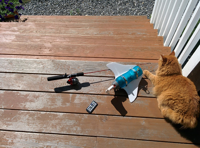
So now I'm just waiting for the chance to take it down to the water (with fishing pole attachment and my trusty sidecat...)

Build Log 8/5/15 LET THE FUN PART BEGIN!!!
While ocean testing revealed the ballasting is far too heavy, it nevertheless revealed a functional mini-ocean glider!!! Unfortunately, I forgot to bring my phone/camera along so I don't have any pictures from the launch but I did take this snapshot of the full build shortly after its successful dive!-

For the next dive I'm going to use two metal ballast bars instead of four, plus it occurs to me that the wings and ballast probably don't require the metal pipe fitting brackets and can just as easily be secured with zip ties. It's possible this may make it too LIGHT of course, but that's easy enough to fix. As I still have plenty of plastic left, I'll also try out a few different wing designs.
Dive Report 8/6/15 Part 1-Too Light...
Glider Version 1.2 eliminated 2 of the four ballast bars and completely redesigned the wing form and tail structure.

I also discovered an unexpected advantage of the corrugated plastic sign board that I've been using for the wing material if the wings are cut with the perforations facing vertically-

The perforations act as mini water funnels providing additional forward motion...
However, it did indeed turn out that the removal of 2 of the 4 ballast weights has made the vehicle too light. This morning's test therefore resulted in a floating glider.

Further modifications should be limited to fine ballasting for which I should be able to use a bathtub. Hopefully, the next ocean dive will take place this evening.
Dive Report 8/6/15 Part 2-Too Heavy Again...
Added some fishing sinkers to the bottom and it went right back to being too heavy again... I'm thinking another design revision might be in order wherein I'll secure both the weights and wings with the same zip ties. That way the weights will also serve to secure the wings in place.

Dive Report 8/8/15
In what I had hoped would be my final design revision, I discovered I could use the metal ballast bars to double as wing clamps by replacing the pipe clamps with zip ties which fit through the holes in the metal bars.

While range of the diving motion was far better than in previous attempts (which either sank right away or floated on the surface), the dive angle ended up being far too steep which caused the glider to tumble over itself...
I tried to add some smaller weights to compensate but that resulted in the overall weight being too heavy.
The problem could be the result of a number of different factors-
- the ballast weights doubled as wings clips may have set the center of gravity too high
- the perforations in the wings may be filling with air and causing instability in the downward dive
- the delta-form wing design may be better suited to shallow dive motions
- the tail may be too tall
- the buoyancy engine assembly may be settling unevenly inside the bottle after it is sealed
Hopefully, I can isolate the problem without having to scratch the ballast/wing clips design. Once again, please do not hesitate to add your input to the comment thread if you have any ideas.
Dive Report 8/10/15
In order to properly isolate any problems, I made sure to adhere as closely to the default design as possible. I set up the glider so I could add additional ballast with rubber bands while in the field, so it wouldn't need to be reconfigured every time.

The above photo shows the glider with small metal wing clamps and two additional metal weights under the wings. This configuration weighs approximately 2 pounds. next to the glider in the photo can be seen the metal weights I added for additional ballast of which each weighs approximately 1/4 pound. @danbeavers had an excellent observation in the comments section that salty water will result in extra buoyancy, and todays dive appeared to confirm this. Starting with no extra weights, added the 1/4 pound weights until the glider sank. This happened at 3 weights (2 3/4 pounds) while the glider still floated on the surface with two weights (2 1/2 pounds). The target weight would appear to be between these measurements.
Questions and next steps
The Sensor Pod
While the purpose of the original Seaglide was the educational value of building it in the first place, the value of such a vehicle within the Citizen Science community would be in the sensor pod. Readers are encouraged to submit ideas using the comments thread and I will update the documentation accordingly.
Design Modifications
The discussion thread in the original post involved whether or not the Glider could be modified to steer itself or receive remote commands. Suggestions include- 1. adding similar electronics to those used on DIY drones including a barometer, GPS and digital compass. 2. Adding a small AIS transmitter configured to transmit its location for retrieval. 3. Attaching a long fishing line-tether to the front of the vehicle to jerk the front around and guide it along a return route.
OpenLRS
Most recently, I became aware of an exciting new open source technology through another project that involves a DIY aerial vehicle. OpenLRSng was originally designed as an ultra long-range transceiver for "FPV" (i.e controlled through a realtime 'first person' video feed) RC aircraft that uses 433MHz on UHF instead of the commercial 2.4 Ghz RC transmitters. I initially became interested in it because it represents an exciting open source alternative to the various proprietary RC control systems on the market. Furthermore, it can even be built from scratch using common, arduino-compatible RF Modules-http://www.rcgroups.com/forums/showthread.php?t=2114859!! The best part in relation to the seaglide project is that it can supposedly TRANSMIT UNDERWATER!!! Further information can be found at the following discussion threads-
http://www.theassociationofmodelsubmariners.com/t83p60-2-4-ghz-and-submarines-also-458-9-mhz
12 Comments
Great Idea! Looking forward to hearing more about how your project develops.
Reply to this comment...
Log in to comment
I would be real careful about changing the buoyancy. Get ALL of the bubbles out of the system. The sign board should not have bubbles. Are there any bubbles in the sign board where you mount the wings to the bottle? Did you get all of the bubbles out of the syringe? I mean both when you adjust the buoyancy and when you "fly" it. What is with that red tail? Are there bubbles in there also? I also believe the buoyancy adjustment is demanding in accuracy. Is the water you are "flying" in brackish? If so there may be a significant difference in density with that and your bathtub water.
The gliders I am familiar with don't continually change their buoyancy. The heavier it gets the faster it falls. They tend to change the buoyancy initially on dive and then again on rise with perhaps some tweaks in between depending on the rate of depth change.
Is this a question? Click here to post it to the Questions page.
Reply to this comment...
Log in to comment
@danbeavers-
Are there any bubbles in the sign board where you mount the wings to the bottle? Did you get all of the bubbles out of the syringe?The close-up image below shows how the perforated sign board fits with the bottle. I split the extreme edge of the wings where they meet the bottle surface to make a tighter fit.
Per the official instructions on seaglide.net, I always hold the glider face-down in the water for two complete cycles in order to ensure the syringe expels any air and fills up with water. In theory, this should also ensure any air doesn't get trapped in the wing holes either.
Considering the Glider has been tumbling from the back-end over the front, there's a good chance that the tail is indeed the culprit! I've tried various tail configurations but with the last one I wrapped the sign-board material with plastic tape to secure it. There's a good chance that this created air pockets!
. Is the water you are "flying" in brackish?The location of my dive is in Potts Harbor/Casco Bay, Maine (Latitude: 43.738511 | Longitude: -70.021706). While I've never done a proper salinity sample (thats a great idea though!) the water here is salty enough that we regularly make our own sea salt by evaporating a seemingly small amount of water. I've always guessed this was because there are no significant fresh water sources in a relatively enclosed natural harbor area, but thats anything but a scientific conclusion. In any case, the salt water would explain why the official recommended ballast weight seems to be too light! From the looks of it, the Seaglide has mostly been tested in lakes and rivers, so it would be a safe guess that the waters of Casco Bay would require more ballast!
In preparation for my next dive, I've cut the wings to the small, square pattern shown in the official instructions and will attempt to match the ballasting recommendations as closely as possible. This way I'll have a good control to test any further modifications. The one major difference is I'll probably leave out the tail piece altogether.
Results will be posted shortly!
Is this a question? Click here to post it to the Questions page.
Reply to this comment...
Log in to comment
Perhaps then you need to adjust the center of gravity. When it is just floating is it right side up and are the wings horizontal? i think I would adjust for that orientation and then see how much syringe movement is required to just change to shallow dive and then shallow climb.
Is this a question? Click here to post it to the Questions page.
Reply to this comment...
Log in to comment
Very nice!
I'm curious how fast the gilder moves through the water. I'm currently working on making temperature sensing boards to use with the Riffle. The thermistors initially used for the thermal fishing bob didn't seem to be fast enough for quicker moving systems (i.e. kayak, sailboat....this?).
By the way, the amazon link to the temperature sensor in the BOM seems to be broken. Here's what I think they're recommending: https://www.sparkfun.com/products/11931
I think this is in the same ballpark of the sensor I'm currently using. I'm wondering if you (or anyone else) has characterized the response time of this sensor? Especially under various methods of waterproofing?
@donblair
Is this a question? Click here to post it to the Questions page.
Reply to this comment...
Log in to comment
@danbeavers- see todays dive report for details but basically I found the glider floats on the surface until I add enough weight to make it 2 3/4 ibs. The target range range is apparently somewhere between 2.5 and 2.75ibs.
@lperovich- I was planning to use a waterproof DS18B20 temp sensor from Adafruit- http://www.adafruit.com/products/381 simply because I already have one. However, the product description is indeed accurate in that the Dallas Temperature Library tends to add a lot of complex code that can be a major pain... I still have a ways to go before I have a workable design for the node cone and sensor pod housing, but I'm thinking of making it in two parts, with the bottom shaped to mount either the waterproof sensor pod or the waterproof case for the Mobius Action Cam that I just recieved from Joovu.com- https://www.joovuu.com/gb/cases/103-mobius-waterproof-case.html.
Reply to this comment...
Log in to comment
Do you know how deep you can take the "waterproof" DS18B20 temp sensor? It may be just designed to take it as deep as the cable is long.
Yes, it is a delicate balance to get the buoyancy correct.
Is this a question? Click here to post it to the Questions page.
Reply to this comment...
Log in to comment
Do you know how deep you can take the "waterproof" DS18B20 temp sensor? It may be just designed to take it as deep as the cable is long -[@danbeavers](/profile/danbeavers)I've never heard of any depth limitations with the ds18b20. Digital temp sensors have different properties than analog devices like the TMP36. According to the product description at http://www.adafruit.com/products/381-
Because they are digital, you don't get any signal degradation even over long distances! These 1-wire digital temperature sensors are fairly precise (±0.5°C over much of the range) and can give up to 12 bits of precision from the onboard digital-to-analog converter. They work great with any microcontroller using a single digital pin, and you can even connect multiple ones to the same pin, each one has a unique 64-bit ID burned in at the factory to differentiate them. Usable with 3.0-5.0V systems.Again, the only major drawback is the additional code involved in parsing the output. Not only do you need both the Dallas Temperature Sensor Library and the OneWire library, but the various library version often have compatibility issues depending on which version of the Arduino IDE you are using. Plus, even though it is a basic concept, I always seem to get tripped up by the pull-up resistor...
Is this a question? Click here to post it to the Questions page.
Reply to this comment...
Log in to comment
I think you miss my point. I believe that if you take the sensor very deep that the waterproofing will fail due to the increased pressure. The adafruit web site does not mention any depth limit thus I suspect it has only been tested by connecting one end or the sensor to a computer and dropping the other end into the water to a maximum depth determined by the cable length. What I understand you want to do is use a waterproof enclosure for the computer and expose the sensor to the water and thus submerge the assembly to a depth greater than the cable length. Thus you may have water intrusion into the sensor resulting in incorrect measurements.
Reply to this comment...
Log in to comment
I assume by "computer" you mean "arduino/microcontroller" unless I gave the impression that I was going for a swim with my laptop? In any case, I did some searching and found that the ds18b20's are often used for marine temperature monitoring where their low cost and chainability allows them to be deployed en-masse.
See here-http://waihinga.ac.nz/foss/university-of-ngakuta/logtemp.htm
and there's lots of research on this blog- https://edwardmallon.wordpress.com/
I can only imagine what calibration must be like in such a scenario! In any case, I've seen no mention of any disortion caused by depth/pressure. There does appear to be some question regarding how well the housing will hold up in a marine environment but such cases involve long strings of the sensors laid out like fishing gear. I was only planning to have the very end of the sensor exposed beyond the sensor pod housing within the Glider's nose-cone.
Don't get me wrong though, I'm not about to go and buy a ds18b20 T-shirt or anything... My past experience with them has involved more frustration then anything else... But again this had more to do with the software aspect...
Is this a question? Click here to post it to the Questions page.
Reply to this comment...
Log in to comment
Great, I doubt you will be going below 10m so ignore my comments. The http://waihinga.ac.nz site has lots of good info that I did not look for before posting.
Reply to this comment...
Log in to comment
May I know what model number of servo motor that u used in the design?
Is this a question? Click here to post it to the Questions page.
Reply to this comment...
Log in to comment
Login to comment.