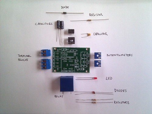
Dual camera kit electronics
Introduction
To get the cameras to trigger simultaneously, we chose to trigger them via USB using a feature of the CHDK.
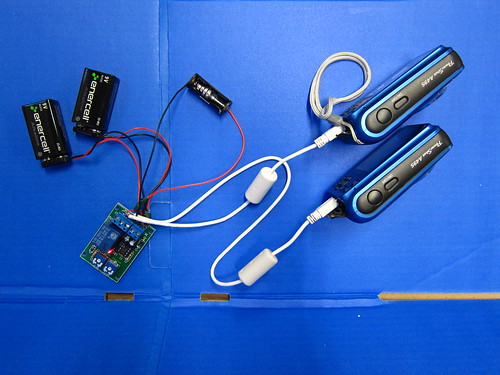
(above, completed electronics setup with dual 9v option)
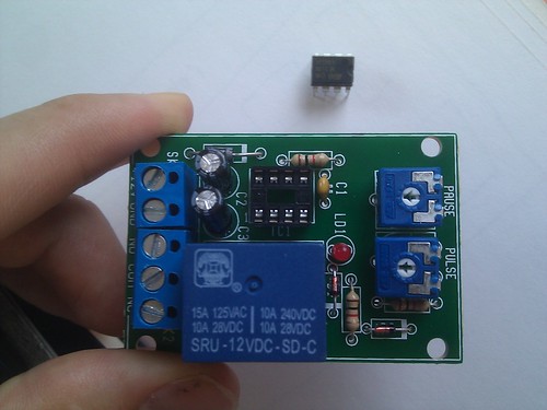
Assembling the 555 circuit
- Pretty good instructions come in the 555 timer package, Velleman model MK 111
- Potentiometer confusion
- Stripping and attaching the USB cables
Connecting the batteries
Battery selection
- Two different batteries are needed:
- a 12 volt battery to run the timer, and
- a 5.5 volt (or more) for actually triggering the camera.
12v battery issue
For the 12 volt battery there are a few options, but since the 12v battery which shipped with the kit seems to be inadequate, we are now recommending two 9v batteries connected in series to make an 18v battery, shown below. This is a bit too much power but it seems to run fine. However, it's a good idea to tape over the exposed leads so they don't short circuit something.
There are other, lighter weight alternatives, such as described by Chris Fastie.

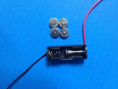

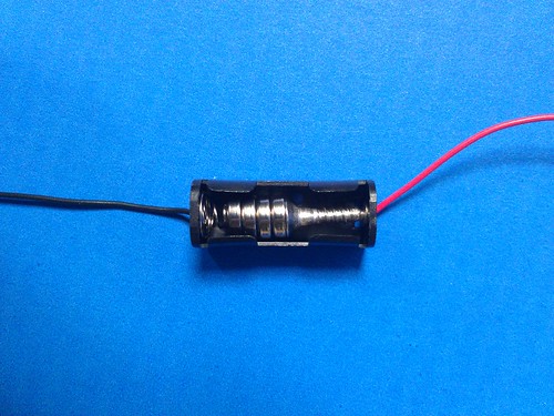
To keep things simple, and because it's hard to find an efficient, cheap and lightweight way to hold 4 cell batteries, here we show how to fit 4 coin cell batteries into an N-type battery holder, which is provided in the dual infrared kit -- using a small wood screw.
This is a bit of a "hack" but has worked very well - 4 1.5 volt batteries is ~6v and very little current is needed to actually trigger the camera.
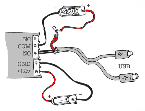
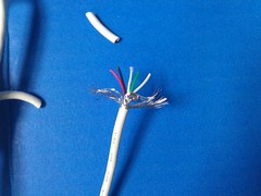
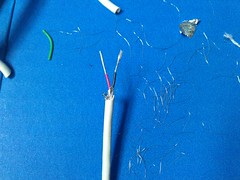
Splicing USB cables
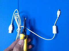
Using a wire stripper, cut at least 8 inches of USB cable, preserving the smaller connector. Strip off the plastic wrapping to expose the smaller wires within and trim away the foil, fine metal strands, and the green and white wires. You'll want more extra wire than shown - maybe trimming to leave an inch of exposed red and black wires will give you some working room. Do this for 2 USB cables, identically.
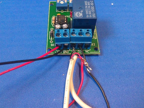
Now, you can take both red wires and the red wire from one of your (N-type) battery holders, twirl them together, and solder them together firmly. Do the same with JUST the two black leads from the USB cables.
Assembly
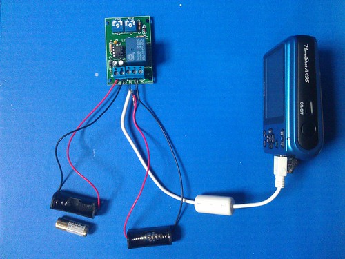
You should be left with two loose black leads: one a combined lead from the USB cables and one from the other end of your battery holder. Place them into the headers of the 555 timer as shown and screw them into place (the screws will hold the wires firmly in the headers. The below images show the old 12v battery (the one without the screw "hack") -- just exchange this for the two 9v batteries in series as described above.
Here are a couple images of the whole setup: