What I want to do
In the comments of this post, we've been exploring how to make an expansion to the open source Visualight board to make it into a thermal flashlight. I had a rough Fritzing schematic but wanted to make a full board we could order with a bill of parts. Here's the original Fritzing diagram I made:

My attempt and results
I tried to make it in Upverter, which allows schematics and board files to be made online. I've never done this before but thought someone else might be able to fix my messy attempts.
https://upverter.com/jywarren/2de9afbe97ada5b1/Thermal-Visualight-shield/
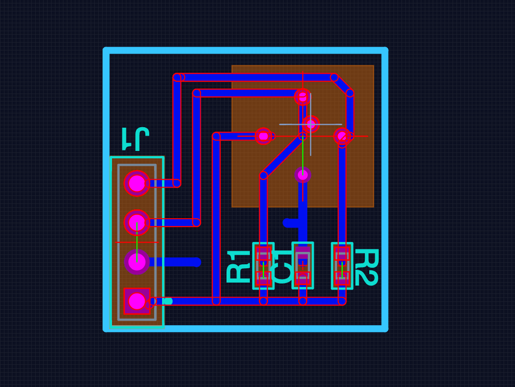
The lead image is the unfinished PCB layout, and here's the schematic:

In the PCB (printed circuit board) layout, I tried to keep things compact, but unless I'm mistaken, we'll need a jumper or a double sided board with a single trace connecting the 2nd from bottom header pin to the top of the capacitor, where I've left a little mark. You can compare to the Fritzing sketch to see what I mean.
For reference, here are the hardware files for the Visualight: https://github.com/lpercifield/visualight/releases/tag/Hardware
Questions and next steps
I hope someone who knows how to use Upverter or something can help out... I'm also not sure if I've spec'ed the parts right or if the spacing of the header pins I've chosen matches those of the Visualight. I'm just new to this.
But we're so close, and at a quantity of 100, this seems to cost less than a dollar per piece for the board ($0.69) and the parts should cost <$10. Assembly, I don't know, but probably not much. The Visualight board at cost might be <$20, then batteries and such. This is looking feasible!
25 Comments
This is cool!
Quick aside: a friend in Amherst makes an open source board, "SquareWear", which is a wearable electronics device that has an RGB led (and a piezo buzzer + light sensor + ambient temp sensor): http://rayshobby.net/?page_id=2686
It also has an on-board coin battery holder, as well as a plug for a small lipo battery -- and an onboard chip for recharging them ...
Maybe we could take his schematic and add the I2C breakout / footprint for the IR sensor?
Is this a question? Click here to post it to the Questions page.
Reply to this comment...
Log in to comment
Also, if it helps: there's an Eagle schematic for the associated breakout board for the IR device on Sparkfun, here:
https://www.sparkfun.com/products/9570
Reply to this comment...
Log in to comment
So I went ahead and mashed up the Rayshobby design with the Sparkfun breakout -- note: Squarewear runs on 3.3V, so the 3.3V version of the IR chip would be required.
Here's the (provisional) result: https://github.com/Pioneer-Valley-Open-Science/thermal-flashlight
Not sure this is the right way forward, but maybe it helps somehow :)
Reply to this comment...
Log in to comment
For what it's worth: I just added a header to the board to break out pins A0,A1,A2,D3, D5, D6, SDA, SCL (the I2C bus), VCC, and GND -- so that folks could wire the device up to other things / boards / an LCD / etc ... updated the board layout here: https://github.com/Pioneer-Valley-Open-Science/thermal-flashlight
Note: my layout can certainly be improved! But at this point:
Reply to this comment...
Log in to comment
Wow, so much progress! Don, if the PL nonprofit subsidized it, would you be able to order this and assemble a prototype to test it out?
Is this a question? Click here to post it to the Questions page.
Reply to this comment...
Log in to comment
Woohoo! Sure thing -- I'll ask Ray re: his process (and if he has any spare components lying about), and get an ETA on ordering a PCB (from OSH Park, I s'pose) ...
Reply to this comment...
Log in to comment
... this is sort of 'mission creep', but: if we add a footprint for a screw terminal and an extra resistor, we could connect up a thermistor -- and this could be a 'thermal fishing bob', too ...
Reply to this comment...
Log in to comment
Cool, I just added a screw terminal footprint, and a footprint for a resistor -- so now it's also a thermal fishing bob device (the board layout in my earlier comment should reflect that now, as it links to the github repo). We could use the Adafruit 10K thermistor (which would mean placing a 10K resistor), or we can e.g. use of these 3K thermistors (requiring a 3K resistor), which are approx $2 when 100 of them are ordered. But we can always decide not to populate the screw terminal or thermistor, if just distributing it as a thermal flashlight.
I'll need to look into whether it might make more sense to use the Leonardo (32u4) chip, instead of the Atmega 328p. Ray is using a cool custom bootloader he wrote himself to allow for USB connectivity to the 328p without any extra silicon; I'll ask him whether that's a good idea in our case ...
Reply to this comment...
Log in to comment
Alright, I've changed the design to use a 32u4 processor (like the Leonardo), based on the Adafruit Flora schematic. The layout isn't quite finished yet, and I should get a second opinion on my schematic ... but this means we can use the standard Leonardo bootloader (I think) ...
Reply to this comment...
Log in to comment
Hi Jeff, I plan to have some of my students make a few simple pcbs to introduce the eagle software and teach some quick and dirty fab methods. I think that the breakout boards that you originally requested would be appropriate for this demonstration. Are you still interested in such a thing? If so, I could post eagle files and could send you the boards that the students make. Also, the board layout in the eagle file that you link to does not look like the layout in the Fritzing diagram. This is important if you want the jumpers to line up correctly. Assuming the eagle file is correct, the jumper has four holes in a line on 0.2" centers. The Fritzing diagram has five holes on 0.1" centers. I am going to assume the eagle file is correct unless I hear otherwise. Jack
Is this a question? Click here to post it to the Questions page.
Reply to this comment...
Log in to comment
Sure, that'd be interesting. Do you think Don's are too complex?
You know, I'm not sure what the spacing is on the Visualight. Do you think you could check it on the Visualight hardware files? https://github.com/lpercifield/visualight/releases/tag/Hardware
Is this a question? Click here to post it to the Questions page.
Reply to this comment...
Log in to comment
Hi Jeff, I downloaded the eagle files that you can get to from the link that you reference and used the measurement tool in eagle to get the header spacing. The holes line up exactly at 0.2" on the eagle file. Do you have one of the Visualight devices in hand? If so, you could check to see if it has the four holes as per the eagle files, or if it has five as per the Fritzing diagram. Whether Don's plan is too complex depends on who is building it. If you are sending it out to be fabricated, then no. On the other hand, not many customers will want to put it together with a soldering iron. I don't know what the fab house will charge you to build these. Whether is is worth it depends on the cost of the Visualight devices and how many you expect to sell. You could put together a kit that has the pcb, sensor ($12.50), resistors, capacitor and header ($1.66). The total should be under $16 and someone with minimal experience should be able to put it together in a half hour. Jack
Is this a question? Click here to post it to the Questions page.
Reply to this comment...
Log in to comment
It has five holes. The Fritzing diagram was a crude reproduction by me, so it's not likely to be accurate. The Eagle files are from Visualight; they're proper.
The interest in Visualight was mainly because it has almost everything needed for the board and has already been produced, and has integrated USB... it's pretty nice and very bright. But Don's board is probably cheaper, though perhaps not as bright.
Reply to this comment...
Log in to comment
And indeed the eagle files also show 5 holes. The Fritzing diagram was actually just a screenshot of the Eagle board file, Photoshopped over a Fritzing screenshot.
Reply to this comment...
Log in to comment
That last comment surprised me. Turns out there are three versions of the board at the github site; The one I was looking at has four holes on 0.2" centers. The one you were looking at has five holes on 0.1" centers. The third has seven holes on 0.1" centers. Do you know where there is a picture of the board that you can buy?
Is this a question? Click here to post it to the Questions page.
Reply to this comment...
Log in to comment
Hi All,
Great discussion here. It sounds to me like designing the breakout board for the Visualight would be an excellent student project, and could also be useful as a thermal flashlight design. It could be used as an external I2C breakout board for use with an Arduino. For that reason, I think it'd be cool to have the student project be to design this breakout board along with a footprint for an RGB through-hole LED -- it could then e.g. be a smaller, independently useful "thermal flashlight breakout for your Arduino" reward in a Kickstarter campaign.
Meanwhile, the thermal flashlight boards I designed arrived over the weekend -- here's a photo:
I'm not even sure that it works yet, as I haven't tried populating the board; and I don't yet know how bright the LEDs will be. But if it does work, it'll have the advantage of combining LEDs, battery recharging circuitry, and a coin battery (or an external battery vis a JST connector) all on a single PCB. It's a surface mount design, so (agreeing with Jack's comment) it's not something you'd want to ask most people to assemble themselves. Depending on how much the Visualight costs, I think it'd tend to be cheaper (and simpler, production-wise) to have everything integrated on one small board -- you don't need to worry about how to connect the external sensor board to the Visualight, or how to include a battery. That said, those are problems that could be fun for the user to solve themselves, too, depending on what sort of arrangement they want.
A growing thermal flashlight ecosystem! :)
I might also be unreasonably excited about the fact that the design that just arrived has an on-board piezo buzzer, too :)
Reply to this comment...
Log in to comment
image broken?
jack - the "diy" version is the one I have, but I dunno if that's the one theyre currently selling. but are the 4 holes we want on the same spacing and order in all 3 models?
Is this a question? Click here to post it to the Questions page.
Reply to this comment...
Log in to comment
Hi Don, That looks really good! Did you order a stencil too? I just had my first experience soldering with paste solder and a stencil, and I was really surprised at how well the board turned out. I'm looking forward to reading the research note when you get this assembled. Jack
Is this a question? Click here to post it to the Questions page.
Reply to this comment...
Log in to comment
wow don!!! is that avr a version with built in USB? could we add a USB dongly thing like the visualight board has?
Is this a question? Click here to post it to the Questions page.
Reply to this comment...
Log in to comment
Thanks Jack! Great to hear re: your surface mount experience. I'm looking forward to trying it out myself. I haven't ordered a stencil -- but that'd definitely be the way to go if the design works out ... there are all sorts of things I may have done wrong at this point :) so I might need to iterate a few times before a stencil is worth it? But maybe it'd actually help assembly so much that it would, in fact, be worth it from the beginning?
Jeff -- yep, it's a 32u4, which has built-in USB! We could certainly add the PCB-USB plugin thingy design, for sure -- but, actually, the experience that folks in the MCHCK have had using such a design with the MCHCK (which has had a similar pcb design) is that a regular USB + cable is a less finicky, more stable (not as cool) option. The MCHCK project is probably switching over to the standard approach, too (and that's what we're using on the Riflfle). But not much cost to modifying the design if we wanna give it a shot!
Is this a question? Click here to post it to the Questions page.
Reply to this comment...
Log in to comment
I wonder if we could do both USB types, at least on the board?
Jack, do you think adding a USB stick thing would be an interesting thing for your students to try to do in Eagle?
Is this a question? Click here to post it to the Questions page.
Reply to this comment...
Log in to comment
Hi Jeff -- great idea! That's how they currently do it on the mchck.org design, too.
For reference, students could use the LeoStick Eagle design files, here:
https://github.com/freetronics/LeoStick
As well as the latest Eagle design files for the latest version of the thermal flashlight board ("REVA"), here:
https://github.com/Pioneer-Valley-Open-Science/thermal-flashlight/tree/master/REVA
I think a good design would be to have the "pcb usb" pads on the bottom of the board, so that the USB connector is still placed on the top, keeping all of the surface mount components on one side of the board -- easier to manufacture at home, and cheaper when outsourcing ...
Reply to this comment...
Log in to comment
Here she is! IR sensor hasn't yet been placed, but here's the basic idea:
https://www.youtube.com/watch?v=nI041unDNr8
Is this a question? Click here to post it to the Questions page.
Reply to this comment...
Log in to comment
woohoo! http://publiclab.org/notes/donblair/02-28-2014/thermal-flashlight-reva-mostly-built
Reply to this comment...
Log in to comment
The "REVA" board looks awesome! It looks like you can get a lot of the components you use at Adafruit now for a good price too, so that might help bring the price down even more. I got a strip of ten bare RGB LEDs for $4 and they even started selling tiny little breakout PCBs to go with them for another $4. I think they even started carrying the Melexis sensors in 3.3v and 5v too. BTW- Has anybody else had any luck getting the original Visualight to work? I got one about a month ago and the only thing I can get it to do is run the thermal flashlight demo code that was posted a long time ago- http://publiclab.org/notes/warren/11-15-2013/visualight-board-for-thermal-flashlights. I can't seem to get the WiFly to work with the custom firmware they wrote to program via the visualight.org web site. I can get the WiFly to work on its own, and I can get the Leonardo to work on its own, but no way to change the color wirelessly... I tried posting on the Visualight forum but it doesn't seem to be active anymore...
Is this a question? Click here to post it to the Questions page.
Reply to this comment...
Log in to comment
Login to comment.