[UPDATE (III/1/18): I found an easier way to build this timer. see: https://publiclab.org/notes/cfastie/03-01-2018/low-power-timer-upgrade]
Adding a low power timer to a data logger has great promise as an easy way to extend the time the logger can operate on small batteries. Rough calculations suggest that a few AA batteries can power an Arduino-based logger for a year or more when a TLP5110 timer controls the current flowing to the logger.

Figure 1. A p-channel mosfet (left) and TPL5110 timer (right). These are the two key components of a timer device that can allow an Arduino-based data logger to operate for many months on small batteries. Ruler hatch marks are 1 mm.
The Adafruit Low Power Logger costs $4.95 (plus shipping) which adds a substantial proportion to the cost of a DIY Arduino-based data logger. So I investigated making my own timer using the same components. The only components needed are the TPL5110 timer IC, a mosfet, and a resistor. Not including shipping, these cost $1.25 per set if you buy 10 of each. So I did.

Figure 2. A SOIC8 to DIP8 adapter (obverse and reverse). These tiny PCBs are intended to allow a surface-mount eight-legged integrated-circuit to be soldered on so it can be used in a circuit on a breadboard. I didn't have an eight-legged IC and didn't want to use it on a breadboard, but otherwise it was the perfect thing (and I had a bunch of them).
Ideally, these components would be soldered to a custom PCB, but that costs a little too much to have manufactured, and I don't have the setup to make my own PCBs. Fortunately, the swag bag from last year's Open Hardware Summit included several SOIC8 to DIP8 adapters which are almost exactly what you need for this project. I didn't attend OHS, but I ended up with some of the swag which saved me a dollar or two per timer.

Figure 3. The TPL5110 and mosfet soldered to the PCB. The traces in the PCB connect each leg of the TPL5110 to one of the header holes on the edge of the PCB. Traces connect two legs of the mosfet (top) to the appropriate two legs of the TPL5110. An added wire (top left) connects the third leg of the mosfet to an unused pin (that's the DRIVE pin which will power the Arduino).
It is a bit of a challenge to solder surface-mount components (they are really tiny) but not too bad when there are just a few to do. In addition to the two ICs, a resistor to set the timer interval is needed. A surface mount resistor would have been neater, but I had only through-hole resistors. I also added a second resistor to calm the DONE line, but testing suggests it is not required.

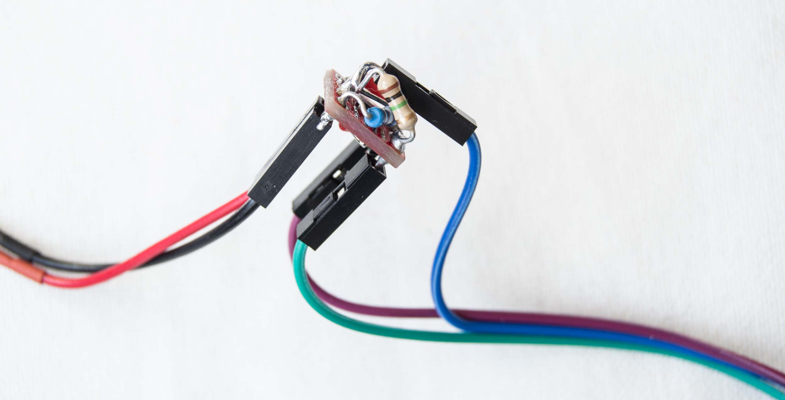
Figure 4. A completed timer. Five wires must be connected to header pins (two from the battery and three to the Arduino logger). Using smaller surface-mount resistors (and eliminating the second resistor) would make it a very neat package.
This DIY timer does not have all the features of the Adafruit version. It is completely up to the task of efficiently controlling a data logger even though there is no potentiometer, tactile button, or LED like on the Adafruit version. But I can't compete with the Adafruit version on price--if I had to buy the little red PCB, the cost of parts would be almost as much as the retail price of the Adafruit product. I'm really impressed that Adafruit can sell their full-featured TPL5110 timer for only $4.95. It's a bargain.

Figure 5. I made a few versions trying different configurations. The next one will be even better. These three function as expected.
I tested the three timers I made and they all work just like the Adafruit version. I'm glad I tried this, although had I instead spent my time driving for Lyft I could have bought all the Adafruit timers I will ever need.

Figure 6. One of my DIY timers was controlling a Mini Pearl Logger in my freezer the other day. A 61.9kΩ resistor set the logging interval at 12 minutes. The graph includes 10 hours of data. My freezer temperature varies a lot more than I thought it would.

Figure 7. Is anyone interested in a kit to make one of these timers? It won't be any cheaper than the Adafruit product, but it is guaranteed to build character and impress your friends.
5 Comments
@warren awards a barnstar to cfastie for their awesome contribution!
Reply to this comment...
Log in to comment
Hi, excelent post!
Is there some config without use of DONE gpio, that make the DRV make a pulse each 8 seconds ?
I want to send a pulse to a gpio processor each 8 seconds!
Is this a question? Click here to post it to the Questions page.
The TPL5110 depends on getting a signal to the DONE pin, so I am not sure it can just send a pulse every eight seconds. The TPL5111 sets an enable pin high every interval (instead of turning power on every interval like the TPL5110), but it also requires a done signal to set the enable pin back to low. But if the microcontroller can send a DONE signal as soon as the enable pin is set to high, then the TPL5111 could work to send a pulse every eight seconds.
Chris
cfastie First of all, many thanks about your answer! And time to answer! You said "But if the microcontroller can send a DONE signal as soon as the enable pin is set to high, then the TPL5111 could work to send a pulse every eight seconds." Sorry, i can do it! My processor does not have free GPIOS :( Can you give some low power solution ? I was thinkg to use PIC12LF to solve that! Thank you so much!
Is this a question? Click here to post it to the Questions page.
It looks like the PIC12LF will do what you need. There is also a low power 555 timer (TLC555) but it is not as low power as the PIC12LF.
Reply to this comment...
Log in to comment
Login to comment.