Driving conductivity sensors seems to be where things get challenging. Straight DC current applied over time causes polarization of the solution you are trying to measure, and causes deposits to build up the posts. Both of these things causes the readings from the sensor to vary and the sensors to fail, sometimes very quickly. There are some good posts about these problems already here on Public Lab that I will try to collect and link. The solution to these problems seems to be to drive the sensor with AC rather than DC. The problem with that comes when you want to make a small, battery powered device that sends data to a DC powered data logger. The electronics to convert DC to AC to drive the probe, and then convert it back to DC to feed input to the data logger are somewhat complex for a novice electronics person like my self.
A simpler solution seems using a 555 timer to simulate AC by switching on and off in an oscillating pattern. It's simpler, but still involves a breadboard full of components that would have to be soldered together on a prototyping board or a pcb if I want to make multiples of this sensor. Doable, but still a bit more of a learning curve than I hoped to spring on a Citizen Science network.
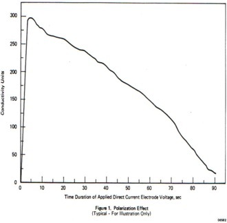
While trying to get up to speed on all the parts of this project I came across this post that appears to offer a different path. Here's what I learned. When DC is applied across the posts of the probe for a period of time it creates polarization that effects the readings in a curve that should look something like this...
.
When taking a continuous reading this drop from 300 down to near 0 in 90 seconds is a problem. Driving the probe with AC solves that problem. But I don't need a continuous reading. I'm just looking for change over a long period of time. I could probably sample once a day and have good information. Once an hour would be a lot of detail. So, if I can apply DC and read at the peak (at about 4 seconds on this graph) and then turn the current off for a while to let the polarization dissipate, that would give me the accuracy without the complexity of generating AC or even wiring up a 555 timer in a 50% duty cycle. Since I am planning to use an Arduino as a data logger anyway, I could also program in the sensor driver to power a pin high for 4ish seconds, read the voltage drop between the posts, and power the pin back to low. This should work for the type of data I want to collect.
Planning to run a continuous DC test taking readings every 1/100 of a second until the current drops to near 0. That should give me a graph similar to the one pictured, and tell me how long my current pulse should be before I take a reading.
Thoughts anyone?

4 Comments
Just wondering if you could simply use an array of readings for some kind of "peak detection" routine in software, rather than leaving it on till the current drops to zero?
Is this a question? Click here to post it to the Questions page.
Reply to this comment...
Log in to comment
Some of the the inexpensive conductivity meters used an a.c. Frequency generator feeding a wheatstone bridge. One leg of the wheatstone was the water solution to be tested. The "balancing" leg was a potentiometer or a resistor bridge. The difference between the legs was adjusted to zero with an a.c. Voltmeter (high impedance). When it read zero, you were there. Some resistance measurements and math would get you there.
The wheatstone part is straightforward, but labor intensive. Using a cheap multimeter would work for the voltmeter. Maybe use the 555 as the a.c. Freq generator?
Just an idea.
Is this a question? Click here to post it to the Questions page.
Reply to this comment...
Log in to comment
I like the simplicity of Camilo Rada's approach to using PWM with a false ground:
https://earthscience.stackexchange.com/questions/13363/are-there-any-diy-conductivity-sensors-that-will-hold-calibration-for-long-perio
Also his DIY graphite probe is one of the best I've ever seen.
Reply to this comment...
Log in to comment
@EdMallon, thanks for the link. Dont know how I missed that one in my search. I'll definitely have some testing to do (as soon as break gets here...)
Reply to this comment...
Log in to comment
Login to comment.