What I want to do
Figure out how inexpensive particulate matter sensors, like the Shinyei, operate, in order to see whether there might be simple ways of improving the sensitivity and range of the device.
The following is based on recent research notes on the topic:
- Willie's great teardown of a Shenyei sensor)
- a post on the DustDuino design
- a post on the Speck particle sensor).
as well as on the nicely commented DustDuino Arduino code, which links to a great description of the sensor being used.
I also found some useful background information in an Arduino forum post on the topic.
My attempt and results

Here's my current (crude) understanding of how these sensors work. Would love to hear thoughts from folks as to whether they think I'm on the right track, here.
Inside the sensor (see Willie's awesome teardown pic above) is an IR LED and an IR photodiode, both pointing at a particular region of air inside the device. There is a focusing lens, to make sure that the photodiode is receiving sufficient light from this region; and there is a baffle in front of the IR LED, to prevent the photodiode from registering light from the IR LED directly.
The basic idea is that the IR photodiode will see IR light only if it is reflected off some particle in the chamber. When there's no particle ...

... the photodiode is reading 'low', as it's not seeing any IR light. But when a particle floats into the chamber ...

... some IR light from the IR LED is reflected off the particle and into the IR photodiode. The IR photodiode then registers a 'high' signal.
If we use a microcontroller like an Arduino, which can measure the IR photodiode signal level every few milliseconds, we can record the amount of time that the photodiode signal spends in the 'high' state versus the 'low' states ...

... and presumably this proportion -- the amount of time the photodiode registers 'high' versus 'low' -- is related to the amount of 'particulate stuff' floating in front of the sensor during any given time interval (a 30 second measurement interval, say).
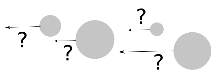
At first I thought: but, ah! This means we can also measure the particle diameter -- 'long' pulses would be 'large diameter' particles, and 'short' pulses would be 'small diameter' particles. Cool!
But then I realized: we're not measuring or controlling air flow through the device. There is a heating element inside the device to encourage air flow -- but we don't really know its effect on air flow (e.g., what if there's a small gust of wind in front of the device at the moment we're measuring the IR photodiode? Or what if it's particularly cold in the room?) ...

So this means that we can't really relate the 'pulse width' in our signal to a particle size -- a 'long' pulse could be due to a larger particle -- or it might actually be due to a very tiny particle taking a long time moving through the beam, because the air flow happened to be low at that moment. Similarly, a 'short' pulse could be due to a large-diameter particle moving through the beam very quickly. Alas.
[Note: I'm not then sure how the Shinyei is able to provide information on two different particle ranges. Perhaps the sensor is applying two different brightness thresholds on the photodiode when registering a 'high' signal -- with the assumption that the brighter threshold is associated with larger particles (more light is reflected)? Any thoughts?]
So then I wondered -- what if we did know the rate of air flow through the device?

If we had this information, maybe we could assess the average air flow during a 'high pulse', and consider that to be the 'rate' of travel of the particle past the photodiode. So then we'd have the rate of particle travel, and the time it took to travel its diameter in front of the sensor (assuming it only went in one direction). Rate ... times time .... equals ... distance! Where 'distance', in this context, is the particle diameter:

Do y'all think this would work?
Some of you may be thinking: well, sure, that might work -- but how the heck are you going to measure air flow through the sensor? Well, look at what I found when searching for 'air flow open hardware':

It's a $17 open source hardware 'hot wire' anemometer from Modern Device that is apparently very sensitive to air flow.
The description on the page:
The Wind Sensor is a thermal anemometer based on a traditional technique for measuring wind speed. The technique is called the “hot-wire” technique, and involves heating an element to a constant temperature and then measuring the electrical power that is required to maintain the heated element at temperature as the wind changes. This measured electrical input is then directly proportional to the square of the wind speed. Hot wire anemometers are available in hand-held packages resembling multimeters, and tend to cost about $300 but this is the first small sensor suitable for electronic experiments. Honeywell also makes larger sensors based on the same principles. The underlying principle that makes the sensor function is the same as the traditional hot-wire technique. This technique excels at low to medium wind speed, and is the preferred technique for sensing indoor air movement, where the spinning cup anemometers typically seen on weather stations are ineffective. As an experimenters tool, the sensor is exquisitely sensitive, with a small puff of air being sensed at a distance of 18-24″. Possible applications include human breath detection, room occupancy detection, hvac system monitoring, weather stations and many more.
Do y'all think we could use something like this device in front of a Shinyei sensor to derive particle sizes -- or at least to calibrate for air flow?
10 Comments
Some of the particle counters I have used in the past worked on a straight, column of air. It looks like your box is more like a mixing chamber than an air channel. The right angles will lead to vortices which prevent some particles from leaving in a timely fashion.
The columns of air are usually channeled through a plastic or glass tube to prevent any vortex problems. The main concern with tubes is that they must be cleaned. One way to diagnostically check when a tube needs cleaning is to run hepa filtered air through the device as a control and check that against the expected clean measurements. If the measurements are too far off, it's time for a cleaning.
That control baseline can be used to adapt the internal algorithm for some level of dirt and grime, but after some point the signal gets lost to the noise of dirt which has deposited on the tube. That's when it is time to clean the tube.
You're primarily measuring reflectance with the orthogonal IR sensor. You might get even more delicious data if you add an IR sensor in line with the IR LED, which would measure absorbance to some small degree. If nothing else, it's a secondary channel of data that can potentially be used with data fusion to reduce noise.
Reply to this comment...
Log in to comment
For reference, I have experience with Hach HHPC6 units (taking them apart, cleaning them, diagnosing their measurement capability, etc). I think your initial design is very similar to what I've seen inside the HHPC6.
There is a huge difference between clean room measurements and outdoor particle sensing. Huuuuuuge. HHPC6 was meant for clean room measurements, but I have fielded them in places they should never go. Filters need to be cleaned daily to weekly (depending), calibrations need to be taken almost as often, and so on.
Don't even get me started on pollen season in New England. Those pine trees could kill every particle sensor I ever fielded.
Reply to this comment...
Log in to comment
The linked anemometer relies on heat differential. I don't see the tech specs, but I'd be worried that in excessively hot environments the background air might not be different enough from the heat element to measure wind speed accurately. If the heating element needs to be 160 F, then maybe I take back my concern. A little black box sitting in the sun during a typical US summer could get quite hot on the inside, especially considering that the other electronics inside are going to generate heat as well.
Both the thermal and piezo anemometers are going to require active energy for measurements, which will sap batteries quickly.
Bladed anemometers are passive. In fact, you could look into a mini-turbine to generate electricity and measure its voltage. The problem with bladed anemometers is that they are going to create an accretion surface for dirt to collect on and could also impede the air flow. If you wanted to use a very small bladed anemometer, you would want to put it outside the exhaust. It would need to be cleaned every so often (unless you drop a hepa filter on the exhaust, which is a common practice for clean room particle counters).
Reply to this comment...
Log in to comment
Would there be a way to create a field or surface coating of the glass flow tubes that prevents accumulation of particles?
Is this a question? Click here to post it to the Questions page.
Reply to this comment...
Log in to comment
It is unlikely that you can do anything to stop deposition, but you could slow it. Not sure what degree of "prevent" you were asking about. There are so many types and kinds of particles in the environment, not to mention gases. Even if you found a treatment that prevented deposition of particles, environmental gases might eat away at the coating. It's an uphill battle no matter how the battle is fought.
I was aware of one project which created a tube of hepa-filtered air which carried the dirty air. It was a very clever prototype, but requires some serious engineering to get it right. Not sure about how well it worked in the end, either. That particular trick might be patent encumbered.
Reply to this comment...
Log in to comment
Instead of trying to measure air flow, you could impose a constant air flow. Chris Bartley said they got better results with a small fan in their Speck. Will this provide the increased interpretability you seek?
Is this a question? Click here to post it to the Questions page.
Reply to this comment...
Log in to comment
I'd say the heater/resistor is used to heat the air sample to avoid condensation in the chamber and on the optics. Also, any aerosol (liquid and solids) will trigger the sample so to avoid liquid interference, like fog, some instruments will heat the intake. However, if you over heat you can burn the particles and change their composition and size. The high-end instruments use a nafion dryer and even those can remove certain SVOC.
Without some sort of fan or pump the intake and exhaust seems arbitrary. I'd look into using a small fan on the exhaust rather than invest in a hot wire anemometer. Look for something with a low energy use because the pump is often the biggest energy draw on the batteries.
I don't see this type of device doing particle sizing but just a total particle reading, which for certain ranges you might be able to correlate that back to a a mass measurement (ug/m3). Particle sizing is usually done with a selective inlet, which I've seen very primitive inlets so that is a possibility down the road but it's a fairly elaborate process to characterize a selective inlet and it's going to require an air pump on the device.
For protecting the optics from dust build up, the common technique is to put an air curtain around the emitter and detector lens. You need a pump to do this too but essentially you draw in ambient air through a filter then pump it into the sensor chamber then let it bleed into the detection chamber through some holes. You do the same with the light source so you need to put a box and window on the source too. I'm guessing this would be cost prohibitive for this but if you want to sample in very dirty environments that's the technique.
Baseline testing with a filter is common (to zero the instrument as it gets dirtier). A HEPA filter is best but you can get away with these little inline coalescing particle filters, McMaster http://www.mcmaster.com/#41575k57/=rt0sep
Reply to this comment...
Log in to comment
Okay, I read the research paper and the heat convection air flow dependent on the sensor orientation.
I also found this report which describes the PM sizing capability. Still skeptical of being able to determine particle size in this unit: http://aqicn.org/sensor/shinyei/
Some more food for thought on aerodynamic particle sizing http://www.tsi.com/uploadedFiles/_Site_Root/Products/Literature/Brochures/3321%20Operation%20brochure%20US-5001468_WEB.pdf
TSI has many published paper too, but I don't have the links handy.
Reply to this comment...
Log in to comment
Those are great links, DavidMack.
The TSI document illustrates the tube of air I was talking about that carries the sample for measuring ("sheath-flow" in jargon). There is sooo much equipment required to do that. A plastic or glass tube should work just fine instead, with caveat of cleaning.
The TSI document also illustrates how to judge particle size based on time of flight (graph on the last page), but that is based on their sensor specifically. Time of flight is a fancy way of saying "how long in the particle in the beam's way," or how wide is the pulse width in the images above. It also mentions some tricky problems with how to tell when multiple particles come through at the same time. Between multiple particles in the stream and a sensor with a slow sample rate, it will be hard to judge time of flight. DavidMack is probably correct in suggesting that the best you can do is calculate a total mass of particulate through the measurement channel, informed by how long the sensor is detecting particulate and how fast the air volume moves past the sensor.
Reply to this comment...
Log in to comment
Bryan, xxv, Chris, Dave -- thanks so much for the fantastic ideas and reflections you've developed here. I'm going to try to digest these ideas over the next few days -- and follow up afterwards with more questions :)
Reply to this comment...
Log in to comment
Login to comment.