
A hardware sketch of our favorite configuration is above. _This is a jointly authored research note. _ @mathew, @stevie, and @warren worked on Thursday on a design for the Oil Testing Kit, which could eventually replace the Desktop Spectrometry Kit. This was based on previous work by @mathew and @warren, but culminated in some great new ideas.
Main goals
Our main goals were:
- reducing # of, or simplifying assembly steps
- adding a sample chamber
- adding UV light source
- simplifying alignment of the light source with the sample and slit
- improving rigidity/weatherproofness/robustness
We also want to try:
- increasing moddability (for power users)
- maintaining or lowering cost of materials (vs. $40 kit)
- lowering weight (which should be easy by dropping the aluminum conduit box)
- combining best of foldable and desktop spectrometers
- reducing light leaks
- improving stability of phone attachment
- accommodating different camera positions
- unify smartphone and desktop kits in some or all features.
With @mathew pushing for a rigid "optical bench" style board where the slit, grating, and camera could be precisely and firmly positioned and affixed, we brainstormed using
- a routed channel and screw mounts,
- a peg board and small right angle aluminum struts pre-drilled,
- a measured grid and instructions printed on it.
- mini binder clips to affix bits of right-angle aluminum struts onto a small platform.
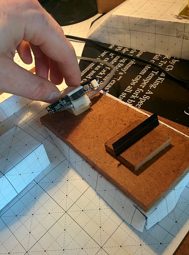
These last two ideas, a measured, printed grid with instructions printed on it for attaching right-angle struts with clips was our favorite. Binder clips are not ideal, but pretty close to what we want. We like the idea that as a flexible platform it not only accomodates modifications in the "optical bench" style-- it invites them.


In past designs, the laser was stuck in a hole next to the sample, so it was impossible to position consistently. Since getting it aligned is a big problem for getting enough light to the webcam, we'd like to fix it completely inside the box, and align it precisely at the best height. to capture the most light, we believe it should be parallel to the slit.
Parts
This is a draft -- and we're working to reduce the # of parts and simplify construction.
- bench - rigid (poplar, basswood, masonite?) sheet on which to clip all optical pieces
- frame - folded chipboard insert which holds the whole system together and provides key geometries
- baffle or envelope - to block light from the outside, matte black paper
- case or box - structural, relatively weatherproof, backpack-proof


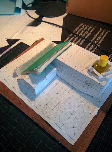
We're thinking about building the light-blocking housing into the spectrometer box. The box becomes a kind of 'sandbox' for setting up a lab setup. Two different strategies arose for the light baffle-- attached to the box, and free standing. We're split on the idea of a folding baffle, and will try a few strategies. Do we fully encase the skeleton or build it into the box?
Holding Lasers
Riffing on a support, the idea of a fold-up support that locks in place at the right height appears good. We'd like to fit the laser entirely within the box.


Earlier
Previously, @mathew & Jeff brainstormed and prototyped a 'skeleton and baffle' designs:
@warren riffed on the same idea with a foldable inside and a sampling station.

13 Comments
Worked on a one-piece frame today while on a phone call...
Issues: hard to get self-trapping fold over corners working, which would eliminate the need for adhesives. This design needs work but is possible with adhesive strips. This is in the actual box we'll use, although a shorter version -- the final will be 3 inches deep.
The slanted side for the phone rest is tough to get stable and the laser pointer harness is also hard to make with snap-together parts with no adhesive. I'm mostly using the fold over and tuck technique that our kit boxes already use but maybe I have to learn more cardboard joints!
Reply to this comment...
Log in to comment
OK, I think if I make the left/right sides fold in rather than the front/back sides, I can make this work out. Posting a sketch in a sec.
Reply to this comment...
Log in to comment
Progress on that slanted joint:
Reply to this comment...
Log in to comment
Working on way to make laser stand from the wall of the box... Hard to keep it sturdy and not use adhesives.
Reply to this comment...
Log in to comment
Ok, maybe eliminated the need for a separate laser holder by shortening the box and using its edge, and constructing a little "booth" which could integrate a window for the slit and a sample hole at the top. The booth needs work but could be part of the folded frame?
Is this a question? Click here to post it to the Questions page.
Reply to this comment...
Log in to comment
Ok I managed to integrate the "booth" with the box for the rigid bench, and in theory they could both be made from the same sheet as the rest of the frame, although that'd make for a pretty large unfolded size. The laser hole may need to be doubled or something to support the laser while there's a bottle in there, or if we make the whole thing of corrugated cardboard maybe it'll be thick enough to form a shelf.
Reply to this comment...
Log in to comment
Ok, thinking about the die cut or lasercut sheet and how this might fit on a flat-mailable sheet. Lots may change about the design but the current layout could fold in half once and mail in a slightly longer than 9.75x12.25 inch mailer:
Reply to this comment...
Log in to comment
Ok, last one for today... On gridded paper for centimeter dimensions, although the folds will need more space if we do corrugated:
Reply to this comment...
Log in to comment
PDF file so far... this is to scale. Works in paper: oil-testing-kit-frame.pdf
Reply to this comment...
Log in to comment
Reply to this comment...
Log in to comment
Wheeee! Cardboard fits like a glove! It needs a couple tweaks for the thickness, longer tabs and for loss due to folding on the angled piece. I also tried using a rubber band to hold the laser tighter although it wasn't really necessary.
Reply to this comment...
Log in to comment
Bench flange and integration concepts.
Reply to this comment...
Log in to comment
oil-testing-kit-frame-0.1.pdf
Reply to this comment...
Log in to comment
Login to comment.