The problem:
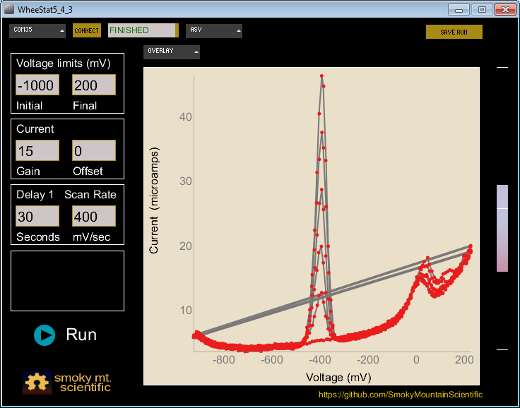
The WheeStat hardware does not provide sufficient voltage to the Counter electrode (sometimes called the Auxiliary electrode) to push the working electrode to its intended limits (+/- 1.65 volts). This can be seen in the ASV scans of Pb2+ containing solutions, below. In this figure, the initial voltage is set in the GUI at -800 mV, but the data does not go negative of -700 mV. Setting the initial voltage to a more negative value will not improve things. For this experiment, -700 is as far negative as you are going to get.

What causes this travesty?
The problem is that the voltage at the working electrode is established by pushing current from the counter electrode and the counter electrode is constrained to voltages between +/- 1.65 volts. If you have the leads from the reference and counter electrodes connected to one side of a resistor and that from the working electrode connected to the other side, then Ohm's law is in effect and driving the counter electrode to -1.65 puts the working electrode at +1.65. When you are working in solution, however, you have something called solution resistance that is very much not governed by Ohm's law and it can take a lot more voltage at the counter electrode to drive the working electrode to where you want it.
So what can be done to improve the useful voltage range?
To get around this problem, we need to get a larger voltage range to the counter electrode. The simple solution is to provide an amplifier and higher voltage source that does that. A simple schematic for such an amplifier is provided below:

So I built a little amplifier board and hooked it up to a WheeStat and looked at the voltammetry of a Pb containing solution. The initial results, shown in the main figure to this Note, looked really good. The instrument had no trouble pushing voltages to +/- 1.5 volts and the baseline for the experiment was flat and reproducible. So far, so good.
So, what is the down side?
Unfortunately, there are a couple of problems with this simple hardware design. First, I had a lot of trouble reproducing the initial results. Later experiments with this and other similar designs gave a lot of noise in the voltage direction (x-axis on the voltammagrams). This arose from feedback between two amplifiers in the counter electrode circuit. This feedback is like having a microphone too close to a speaker and it set up a sine wave in the voltage signal that should not have been there. While it should be possible to damp down this unwanted signal using a low pass filter, that introduces more complexity into the booster circuit and further limits the time scale of experiments that the resulting instrument can run. The second problem with the circuit arises from putting a +/- 12 volt source into a circuit with electronics that are only rated for 0 to 3.3 volts. While the instrument should not self-destruct as long as the circuit is maintained, it is pretty easy to screw up. Removing an electrode from solution, or having an alligator clip come off) disrupts the circuit and will cause voltage spikes that will kill sensitive parts of the electronics. Right now, I have a bunch of fried electronics littering my work bench.
Summing it up:
In short, the principle of increasing the driving voltage will improve the useful voltage range of the instrument, but further work needs to be done on the hardware. While I would like to have an add-on component that fixes this issue for existing WheeStat hardware, the simplest solution will probably be to redesign the instrument. In the past week, we built a prototype for a next generation WheeStat that looks like it will solve the above problems.
0 Comments
Login to comment.