Oil testing kit Beta programme - Assembly notes Part 3: spectrometer
Contributors: @TedF and @cindy_excites
Date: 31/Oct/2015
Here we document our experience assembling the spectrometer frame and put forth a few humble suggestions.
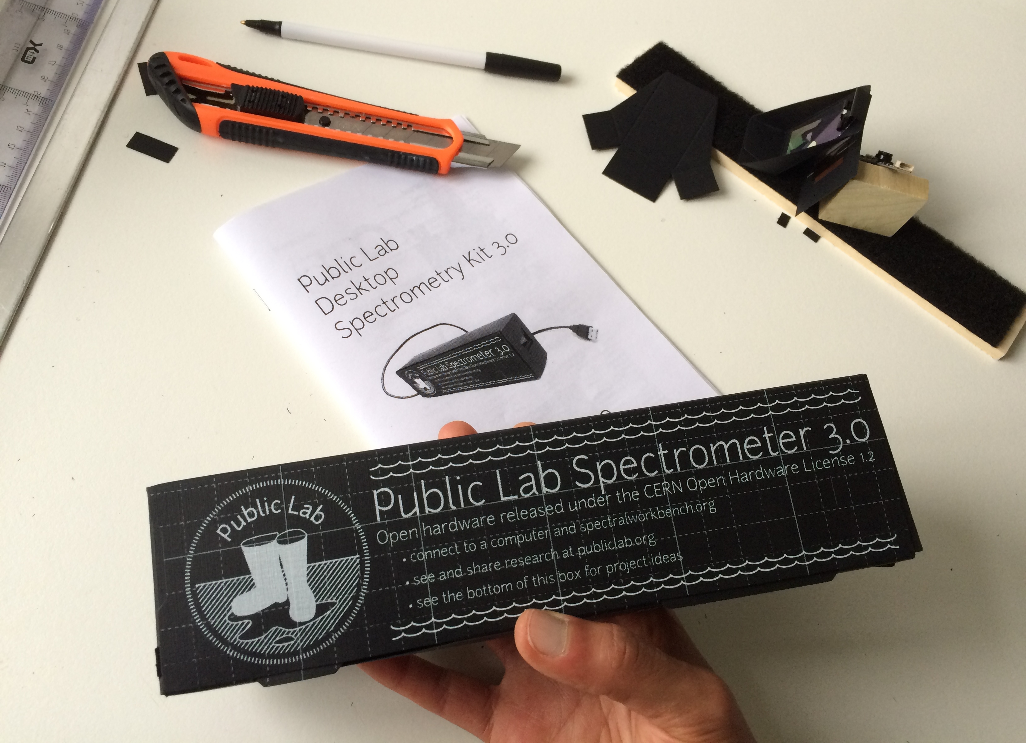
1) Bench assembly Following the instructions on how to build the Desktop spectrometer Kit 3.0, we started by taping the 'loop tape' to the 'ash bench'. The instructions feature an image with a narrower version of the tape:

This is the new wider tape that came with the kit:

NOTE: To apply the loop tape, we placed the tape near the edge of the ash board and the slowly peeled-off the protective tape layer, allowing for an easy way to guide the tape onto the board (which would otherwise be difficult to remove in case the tape is laid down crocked). We also cut away the overhanging bit of loop tape:

2) Camera block assembly
i) Here we reverse the steps by attached the 'hook tape' to the block first:


NOTE: Being a bit wider than 2cm, the two pieces of hook tape overlap slightly in the middle.
ii) We then prepare the camera for mounting:

NOTE: We adhere two sides of double-sided tape. Rationale: one tape down the middle might cause the camera to wobble from side to side; two tapes provide stability.
iii) We attach the camera to the block ensuring that the camera's board is flush with the base of the block (otherwise the height of the camera might be blocked by the top part of the 'mid-point' hole of the 'diffraction grating angle' (see construction of this part below)).

3) Making a diffraction grating from a DVD
The instructions of this are very good. Very smart to start with "Do not touch the surface of the DVD" ;).
As note in our calibration research note, we had qualms about the DVD fragment's quality due to unsatisfactory separation. If the quality of the DVD fragment turns out to be problematic, I'll try @ethanbass's recommendation with MrBumper's method ).
Our qualms was due to our DVD not having been peeled/separated properly (even after several tries, the DVD that came with the kit was rendered unusable so I used one from an unopened DIY foldable paper spectrometer, which proved to be more resilient):

Does it matter if it still refracts the light? What is good enough for a DVD fragment? Here is our piece of DVD:

4) Assembling the diffraction grating angle
Upon seeing the design, I wondered what inspired it. Maybe a direct link to a development research note on this would be nice for the incurably curios ;).
i) We used two strips of double-sided tape when taping the three flaps together.

Conveniently, the hook tape fits perfectly on the base of the diffraction grating angle.
ii) We place the DVD fragment on top of the mid-point hole in the diffraction grating'. We have to admit that since we did not understand why the DVD fragment didn't have to cover the whole of the 'mid hole' of the 'diffraction grating angle' I covered the whole thing. (Might be good to add info to answer 'why is the outer edge of the DVD used' and 'why is one half the mid-point hole covered'?) And we remove the handles from the binder clip:

5) Assembling the slit card
Also great instructions for this. We aligned the collimation slit with the line on the slit card as best we could:

The design for sliding the collimation slit card is brilliant!

6) Assembling the box

The assembly video is excellent! And very well complemented by the photo-based walk-through.
We only had two little hiccups.
The first was that one of the folds was not pre-marked. To facilitate the folding of this flap we slightly ran a cutter along the cardboard using a ruler:


The second hiccup was making the mistake of not carefully reading "Make sure the small rectangular holes on the top and bottom of the box line up. We will put the webcam cable through that hole later." And also missing the concomitant photo that states "Align holes here"…
So we document our 'error discovery' here:


7) Final steps
i) A little note on leaving a gap between the edge of the ash bench and the camera block might be good to add, rationalising the space needed for the smartly suggested knot on the cable.


ii) Inserting the bench and connecting the camera's cable:

And the left over screw this time is…

(Where does this go??)
This was a very satisfying assembly process. It is very enjoyable to go along with Aha! moments at every step realising the rationale behind the intricate design! Thank you for this!
Other research notes in this series:
Oil testing kit Beta programme - Package content
0 Comments
Login to comment.