# Riffle Design Philosophy
The [Riffle](http://publiclab.org/wiki/riffle) is a collection of designs for an open source approach to water monitoring.
The original Riffle design was a [ARM-based datalogger board enclosed in PVC](https://github.com/bgamari/riffle); [Public Lab](http://publiclab.org/wiki/riffle) has supported development of an [Atmel328-based datalogger enclosed in a water bottle](https://github.com/OpenWaterProject/riffle_328).
By now, several instrument designs have been constructed around the Riffle, some of which of are described in an array of Github repositories:
- [Openwaterproject](https://github.com/OpenWaterProject) -- the main organization on github
- [riffle_328](https://github.com/OpenWaterProject/riffle_328) -- hardware designs, instructions and software for getting started with the Riffle_328 datalogger
- [riffle_328-conductivity](https://github.com/OpenWaterProject/riffle_328-conductivity) -- Design considerations around conductivity
- [riffle_328-depth](https://github.com/OpenWaterProject/riffle_328-depth) -- Depth measurement circuit prototype
- [riffle_328-turbidity](https://github.com/OpenWaterProject/riffle_328-depth) -- Turbidity sensor prototype
- [riffle_328-thermistor](https://github.com/OpenWaterProject/riffle_328-thermistor) -- Connecting a thermistor to a Riffle
- [riffle_328-i2c](https://github.com/OpenWaterProject/rriffle_328-depth) -- Connecting i2c sensors to a Riffle
- [riffle_328-one-wire](https://github.com/OpenWaterProject/rriffle_328-one-wire) -- Connecting one-wire sensors to a Riffle
The following document attempts to detail the various design considerations involved in various aspects of the Riffle design throughout its development to-date.
# Motivation / Background
The initial concept for the Riffle came out of conversations with Mark Green, a Professor at Plymouth State, about the current technologies used for water monitoring.
Water monitors have widespread use in hydrology, pollution monitoring, and many other fields in which water quality and water conditions are of interest. In the context of pollution monitoring, water monitors are useful for:
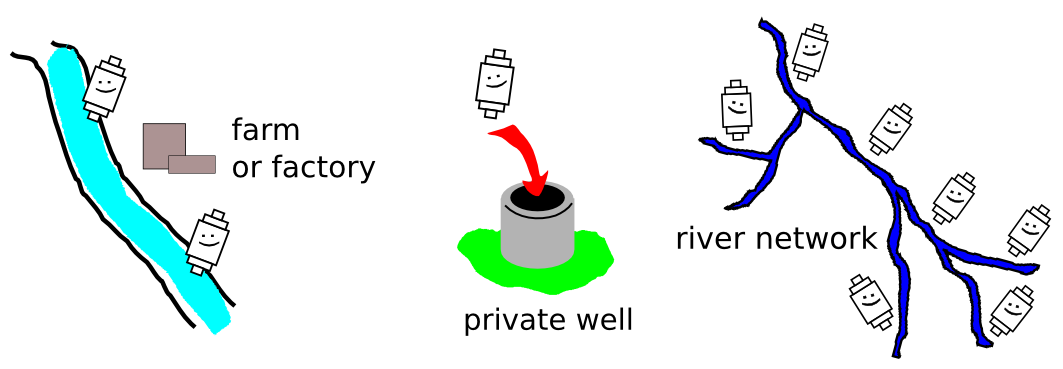 - Identifying and locating point sources of pollution along water bodies like rivers and streams;
- Monitoring the water height and water quality in remote wells;
- Assesing the impact of farming on bays and lakes;
- Many other related applications.
As a hydrologist, Mark has used various water monitoring technologies in his research for many years. Mark was interested in the possible use of 'open source hardware' in water monitoring, and identified for us some of the main challenges presented by the current, dominant commercial designs:
- **Proprietary data format.** Most commercial systems record data in an encrypted format that can only be decoded by their proprietary software.
- **Proprietary software suite.** The software required to interact with the hardware is itself proprietary and 'closed'; only the company selling the software is capable of improving the software or fixing bugs, and often the development cycle is slow.
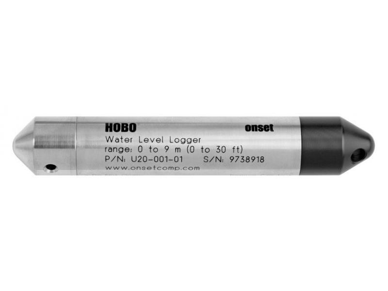
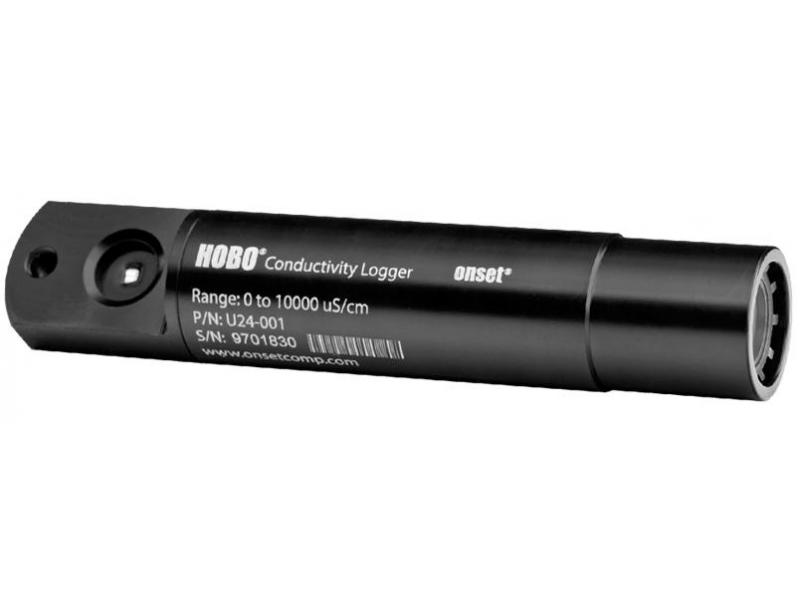
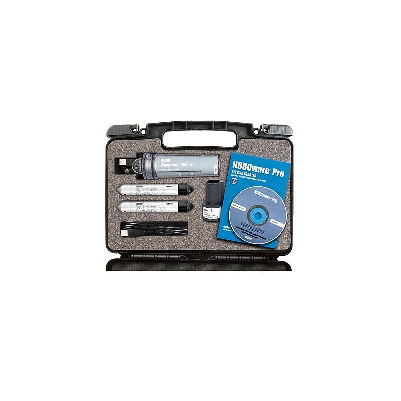 - **Proprietary hardware.** Typical commercial water monitoring hardware requires special hardware dongles' in order to retrieve data from the device. The monitoring hardware itself is often of high quality, but modifications or the additional of external sensors is not allowed or supported.
 Around the same time, Chris Fastie, a forest ecologist familiar with the use of dataloggers in forestry research, wrote up an [assessment] of the qualities that an open source datalogger might usefully have in order to provide a useful alternative to current commercial solutions.
In general, the impression emerged that while solid, thoughtfully engineered monitoring solutions exist, they typically are not designed to allow for modification, innovation, interoperability, or easy data sharing.
# Project Goals
As a result, we decided to begin a project to develop an 'open hardware water monitor', useful for some common water monitoring applications. We sought to make something which would have the following characteristics:
- **Low power**. Capable of monitoring at a remote locations for many days -- weeks, at least -- on a battery.
- **Open source hardware.** We hoped to leverage the world of open source hardware electronics, and see if we could build a basic water monitor device that allowed for easy hardware modification and reprogramming, and easy for people to add new sensors.
- **Open source software.** We aimed to develop simple ways of transferring, visualizing, and analyzing the data collected by these monitors.
- **Open and accessible data formats.** We also planned to design the device so that it could output data in a common data format (CSV), using accessible data storage media (SD cards).
- **Accessible materials.** The water monitor would require a waterproof enclosure -- our aim to was to construct this enclosure, to the extent that was practical, from materials that could be sourced / replaced locally, in order to reduce costs and enhance accessibility. The circuit design should use components and a process that would be easy for others to replicate themselves.
- **Encouirage a large community of users.** Our hope, too, was to establish a community around such a device, so that hardware users could support one another's efforts, help debug code, and share new designs.
# Overview of Design Parameters
Below, we describe the main components of the Riffle design, broken up into categories. While some of these categories have inherent overlap -- for example, the circuit board design is intimately related to the choice of enclosure shape -- this division seems to provide a useful way of seaprating out tractable components of the design problem we are attempting to address:
[**Enclosure**](#enclosure). The container for the water monitoring electronics.
[**Circuit Board Design**](#circuit-board-design). Design considerations around the 'printed circuit board' at the heart of the water monitor.
[**Power and Battery life**](#power-and-battery-life). Choices made in order to reduce power consumption on the device, in order to enable extended monitoring in the field.
[**Sensors and Modularity**](#sensors-and-modularity). Choices made about the enclosure and circuit board design in order to allow for the main sensing applications of interest.
[**Storage and Data Retrieval**](#storage-and-data-retrieval). The various mechanism in the Riffle design for data storage and the associated modes of data retrival.
[**Pinouts and Bus Interfaces**](#pinouts-and-bus-interfaces). The electronic inputs and outputs afforded by the circuit board design, some of which are associated with specific, common bus protocols used by common sensors.
[**Data Analysis**](#data-analysis). Considerations for making analysis of the data acquired by open hardware water mointors easier to analyze and share.
[**Development Workflow**](#development-workflow). The workflow we envisage around curated designs, code, and data on Public Lab and Github.
[**Similar Projects and Future Directions**](#similar-projects-and-future-directions). A brief listing of projects with similar goals, and possible next steps for Riffle development.
Each of these categories is elaborated upon more fully, below.
------------------
# Enclosure
One of the first discussions around the water monitoring design was: **how will we make the electronics waterproof?** All of the commercial solutions involve fully custom enclosures, usually made from (initially) expensive metal or plastic molds. In contrast, we hoped to enable users of our design to source their own enclosure parts locally -- both to reduce cost, and allow for easy modifications / extensions / variants of enclosure designs, associated with novel applications.
The two main enclosure designs that presented themselves used:
- **PVC**; and
- commonly-available **water bottles**.
### PVC
PVC pipe is used around the world for transporting liquids; it is inexpensive, and widely available. It is also already used extensively in hydrology and other fields as a structure for enclosing water monitoring devices (as a sort of 'secondary' enclosure that secures a commercial water monitor in place, and/or controls the flow of water over the water monitor sensor surfaces).
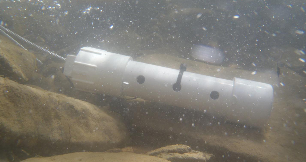 This material was thus an obvious first choice for the RIffle enclosure. Our initial approach was to identify the minimal set of PVC hardware that would:
- protect the sensitive monitoring electronics
- allow for sensor hardware to be mounted externally, and communicate through the enclosure to the datalogger
- allow easy access to the internal compartment such that the container could be reused between servicing / battery replacement.
We found such a minimal enclosure at our local hardware store, consisting of two screw end-caps and a connecting middle piece.
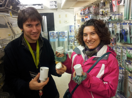
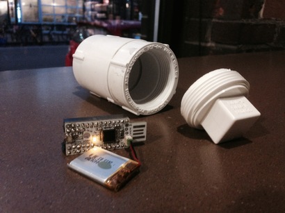 The basic idea was then that the main datalogger electronics would sit inside the waterpoof enclosure; and we would 3D print a custom 'endcap' that would fit around the end of the PVC and house the sensor electronics.
 The 3D printed end-cap was designed in OpenSCAD.
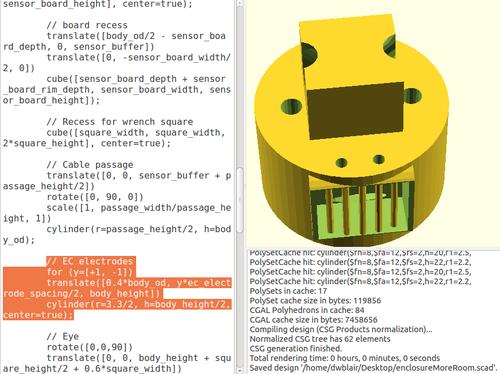
 The associated electronics was held in place and sealed by potting it with epoxy.
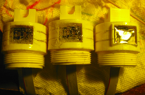 We found that this design had several issues:
- The 3D printed material was not easy to make consistently waterproof. Efforts to use epoxy to seal the 3D printed cap were unsuccessful.
- The dimensions of the PVC end-cap fluctuated significantly, so that the 3D printed part did not always connect nicely without extensive modification.
- Sealing the expoxy (the one we were using) seemed difficult without a careful 'baking out' process, which seemed to result an a relatively inaccessible design.
### Mallon enclosure
Subsequently, we have noticed that Edward Mallon has developed a [much more elegant PVC enclosure approach](https://edwardmallon.wordpress.com/2015/02/04/a-new-diy-underwater-housing-for-2015/), involving PVC parts that maintain a watertight seal through a 'gasket' and -ring configuration, so that accessing the internal electronics to change a battery and resealing the device become much easier:
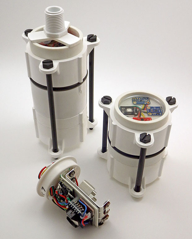
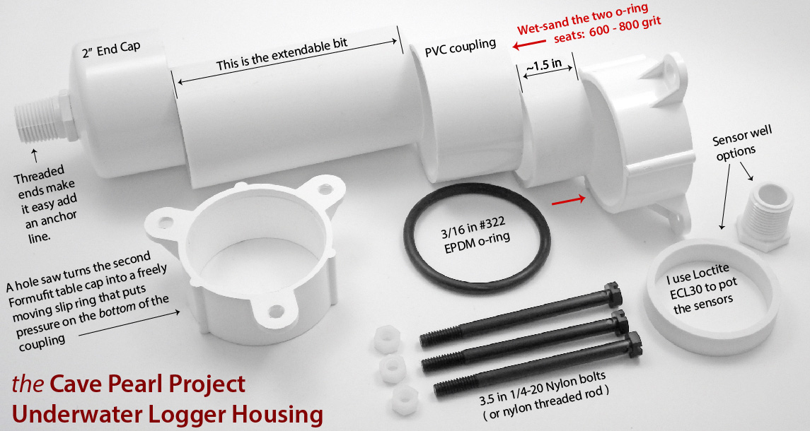 This design seems to be a robust PVC enclosure (Mallon's design has lasted several months underwater), with parts that are accessible online; the end-cap arrangment allows for sensor modules to be mounted in an accessible 'platform' configuration.
### Bottle
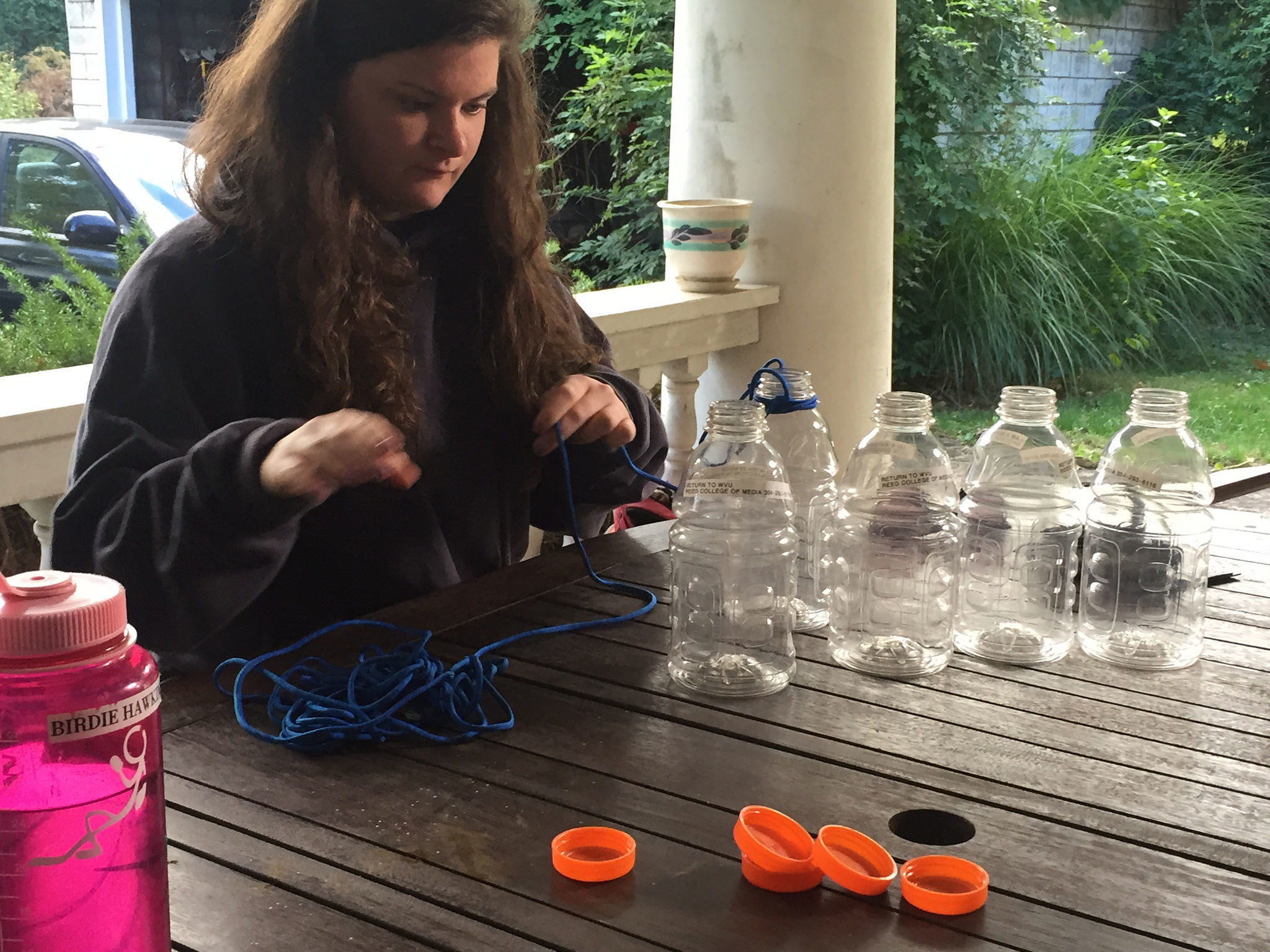
After having trouble sealing our PVC enclosure and coming up with a good way of connecting our datalogger to external sensors, we happened upon the idea of containing the electronics in commonly-used plastic water bottles.
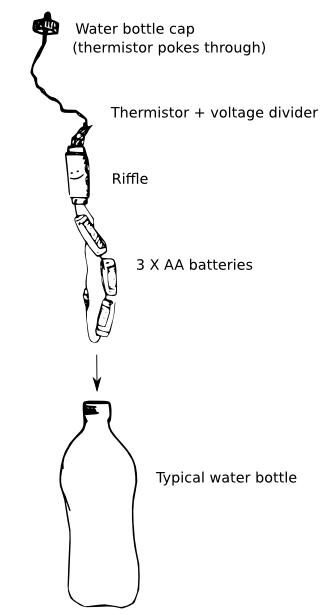
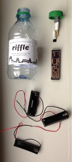
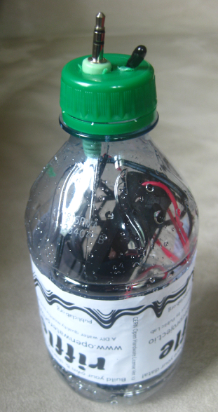 This design idea seemed to offer the following advantages:
- The enclsoure was readily sourced nearly anyhwere in the world
- It would be a compelling ['detrivore'](https://publiclab.org/wiki/detritivore-design-by-mathew-lippincott) reuse of waste materials
- The enclsoure was likely easy to seal successfully
- Key applications of the monitor -- measuring temperature and conductivity -- might be accomplished by simply sticking probes through the water bottle cap.
Several variations on this water bottle enclosure were then developed. Some of the ideas explored were:
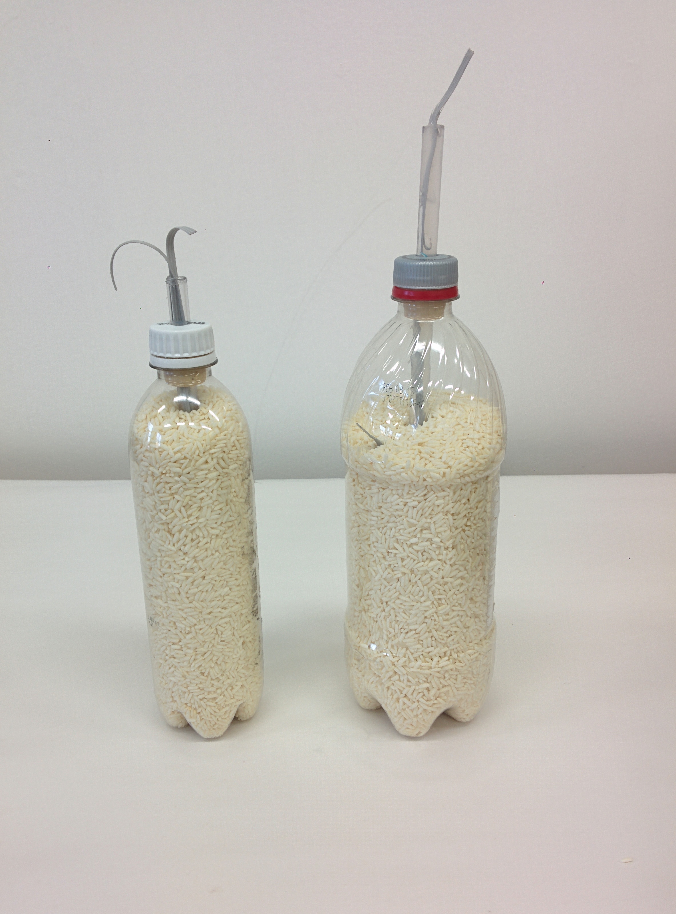
- Using rice or mineral oil to protect the electronics against water leaks or water pressure
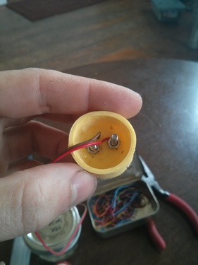
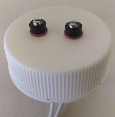
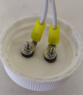
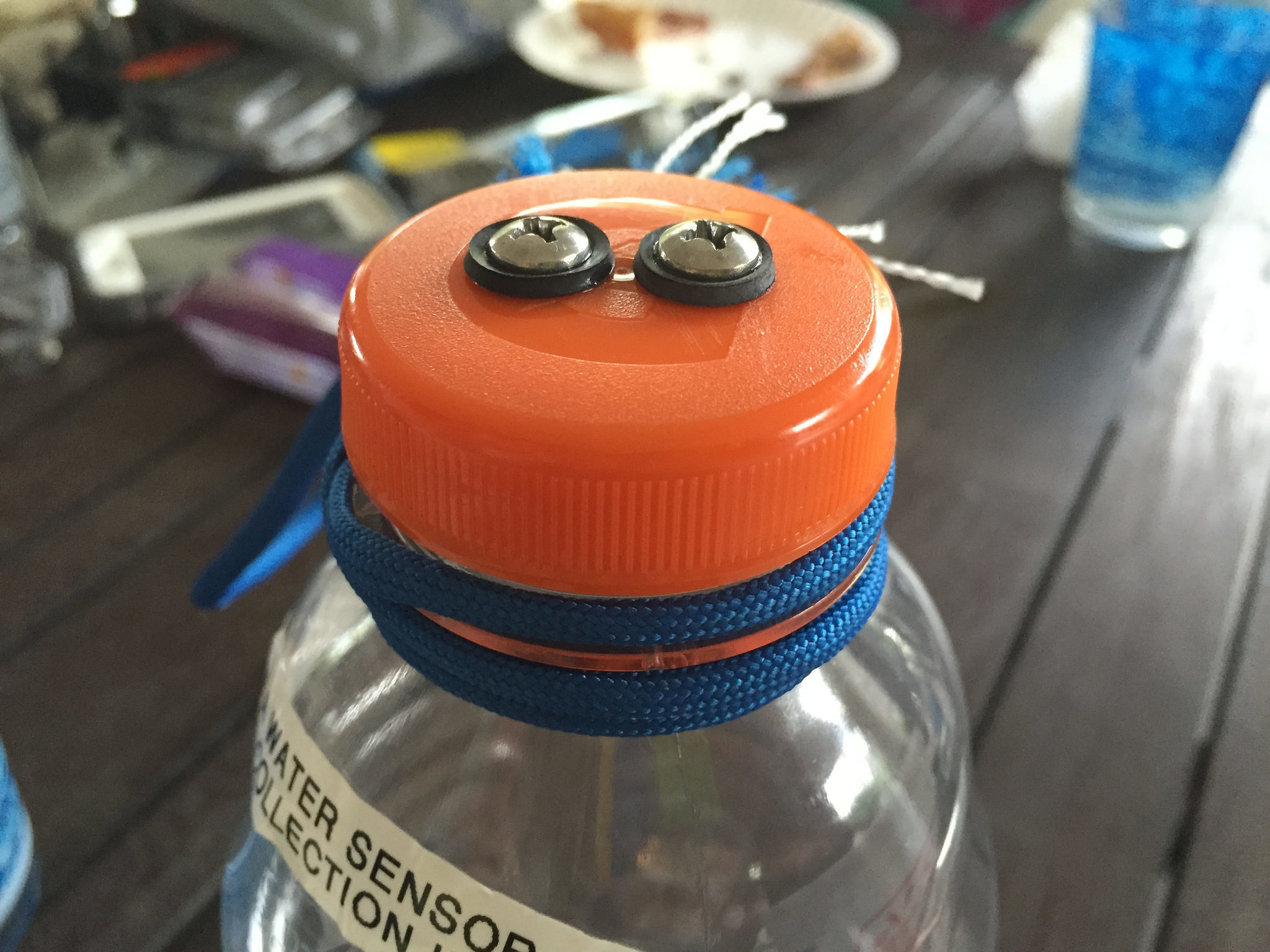
 - Using screws through the bottle cap to monitor conductivity:
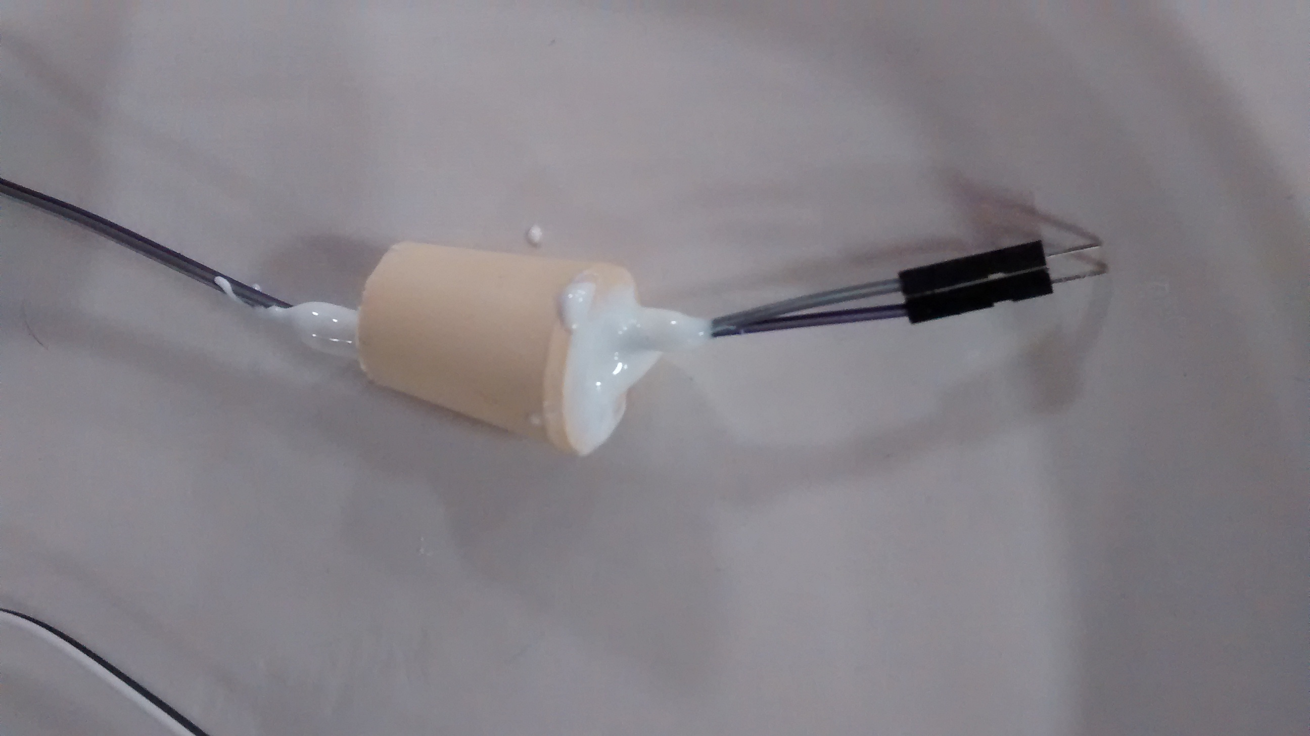
 - Using a rubber stopper in lieu of a plastic bottle cap, in order to create a 'gasket' seal and allow for wires and other sensor materials to be sealed into an opening more readily:
 - [Custom water bottle caps](https://publiclab.org/notes/mathew/01-16-2015/sketching-a-waterproof-pop-bottle-sensor-system) that could house sensors and affix them to the end of the bottle securely.
- Various [other ideas](https://publiclab.org/notes/mathew/02-26-2015/sensors-in-soda-bottles).
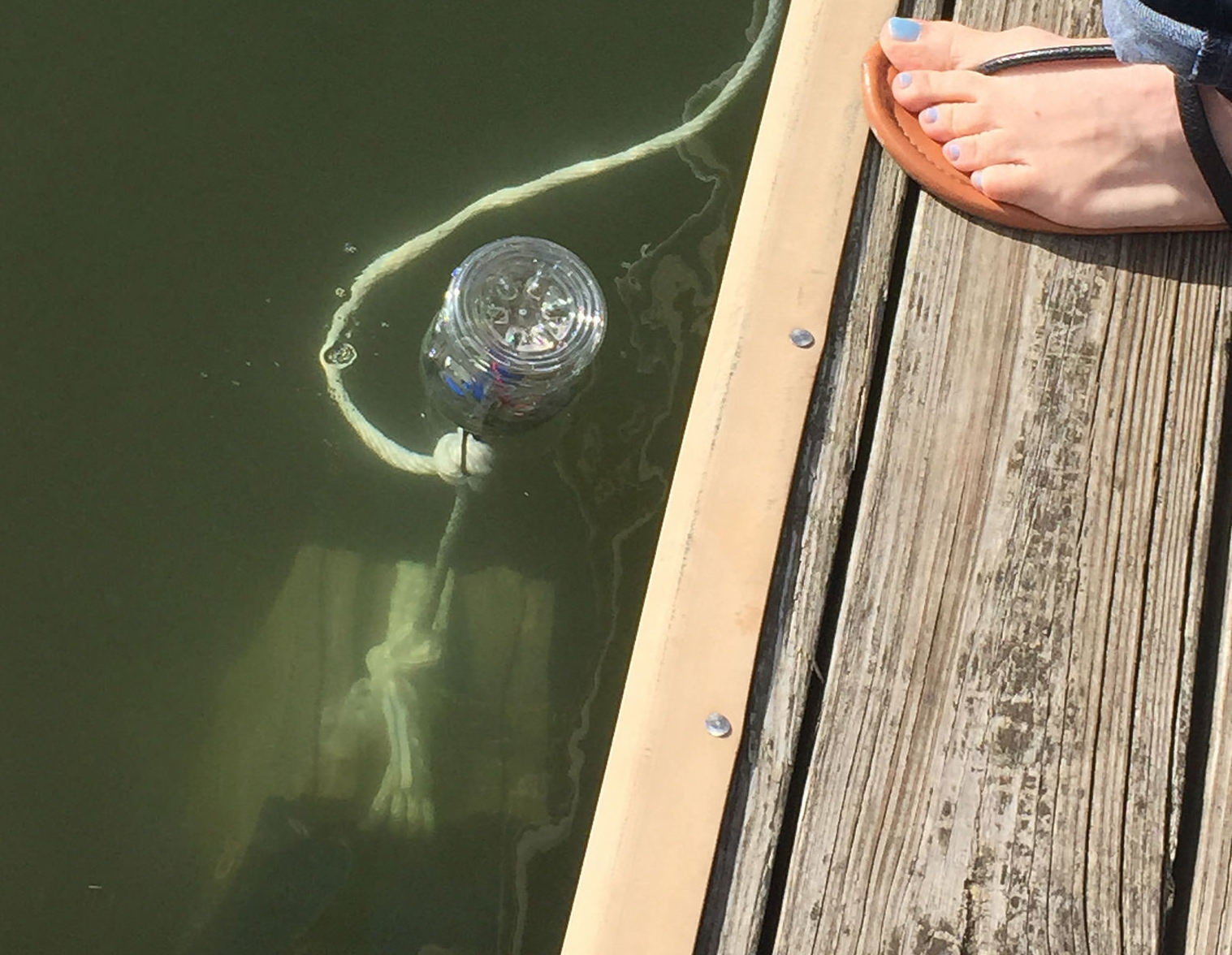
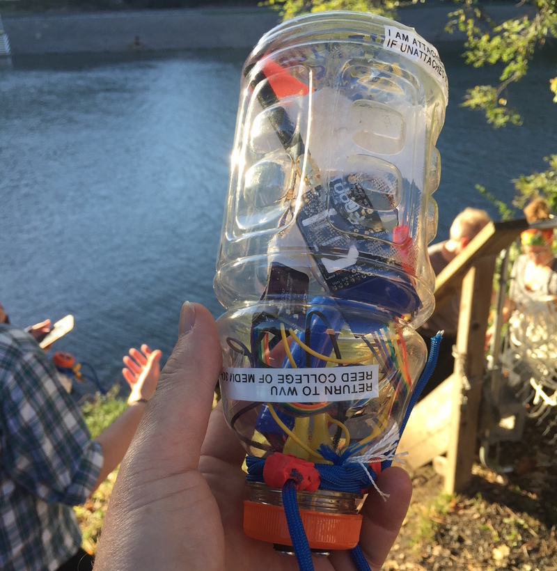
The water bottle approach was used in John Keefe's ['sensor journalism' deployment](http://johnkeefe.net/monitoring-the-monongahela) in West Virginia with good success, resulting in several-week deployments of sensors underwater.
 The shape of the water bottle also allowed for anchoring a weight to it fairly easily in order to keep it below water:
 ### Other
In the course of Riffle development in the Public Lab community, other enclosure ideas of been proposed.
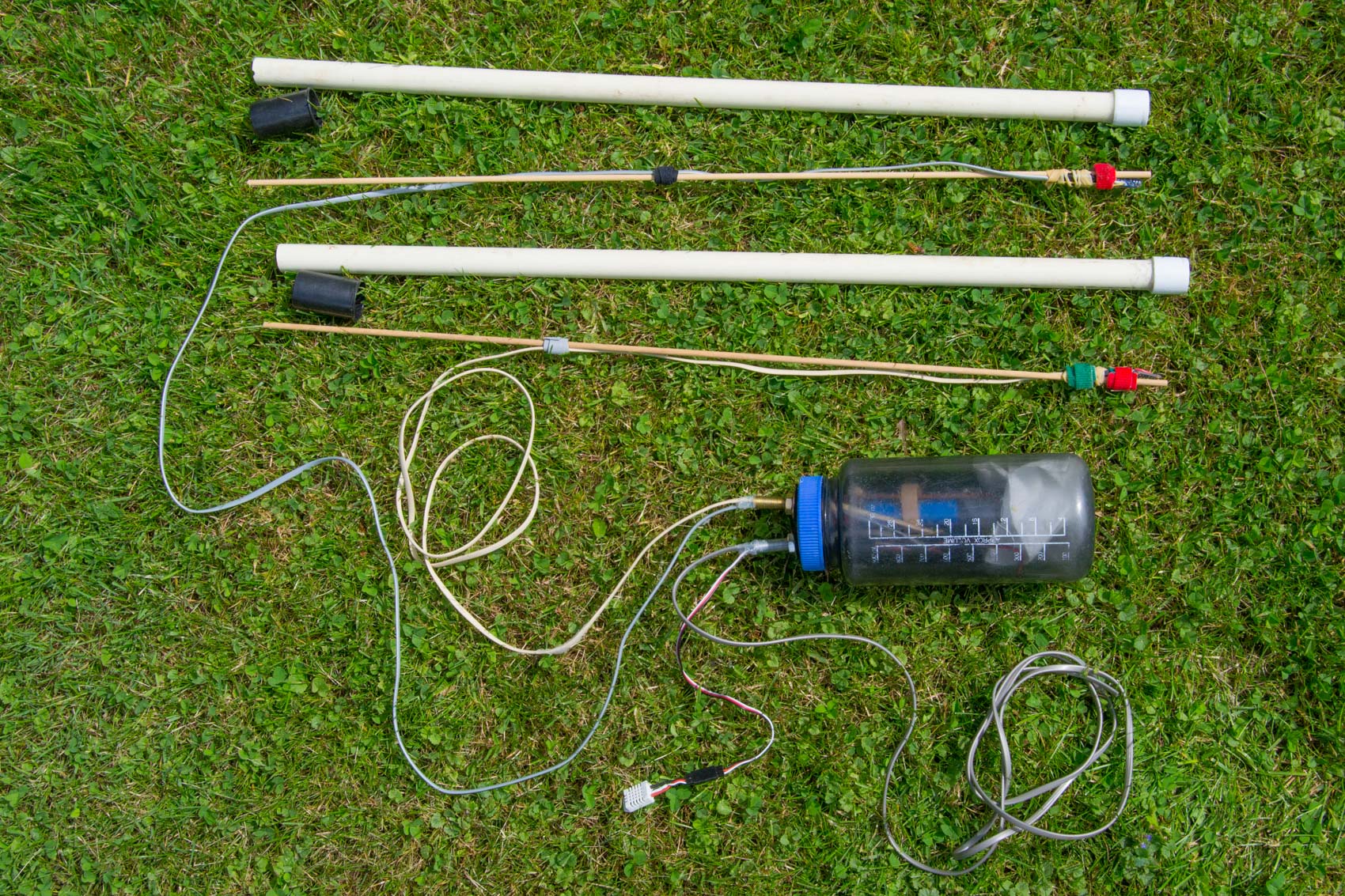
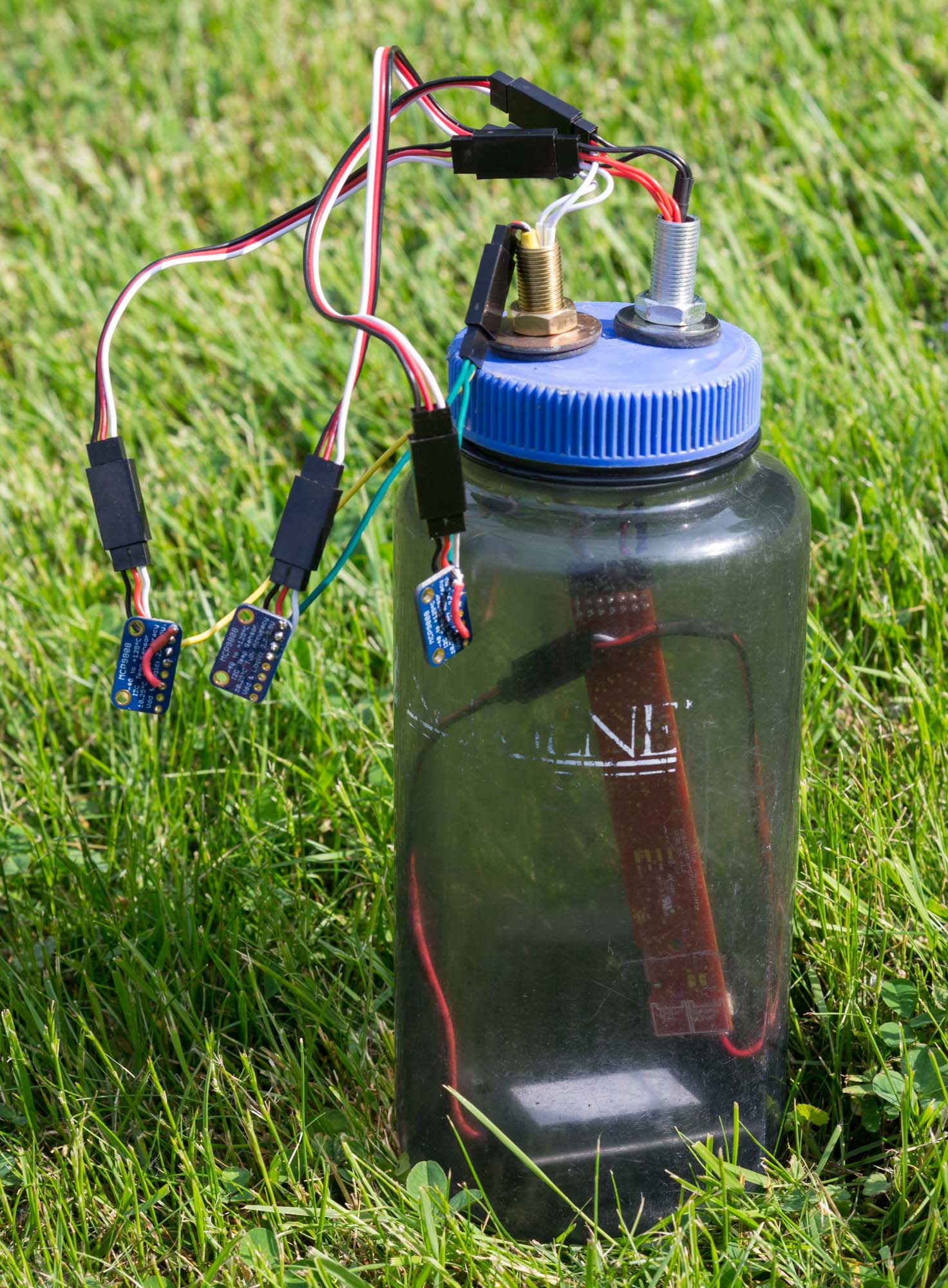
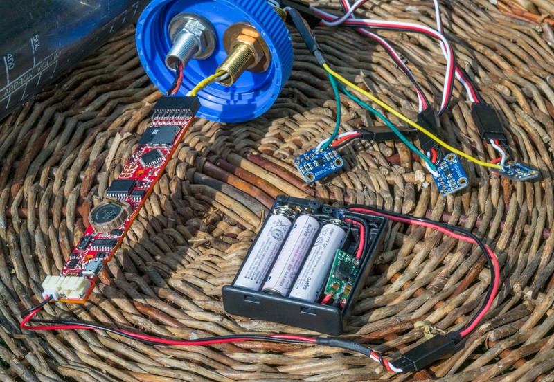
**Nalgene bottles.** Chris Fastie focused on a [Nalgene-based design](https://publiclab.org/notes/cfastie/05-27-2016/riffle-campout). The larger size of the Nalgene bottle mouth allows for the use of a standard AA battery enclosure, and makes it relatively easy to create multiple pass-throughs:
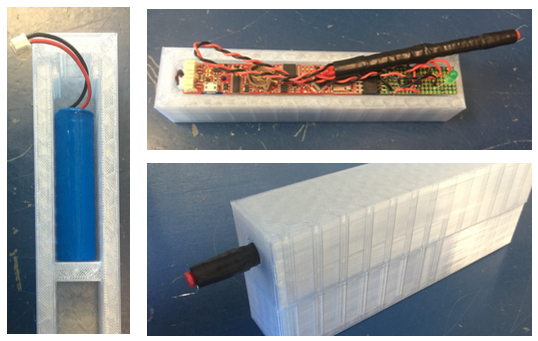
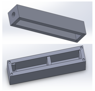
 **3D printed enclosures**. Rebeccah [posted a design](https://publiclab.org/notes/rebeccah/08-29-2016/riffle-device-water-conductivity-sensor) for a 3D printed enclosure that contained compartments for both the RIffle and a lithium ion battery; it also has recesses for magnets to keep the enclosure shut:
 Several other designs are likely possible. We're eager to see further novel enclosure designs developed, tailored to particular applications and leveraging locally-available materials.
# Circuit Board Design
### Initial inspiration: MCHCK
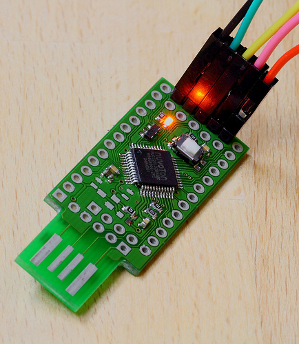 The first Riffle design by Ben Gamari and Laura Dietz leveraged an open source microcontroller design, the [McHck](https://mchck.org/). The McHck, designed around the same Freescale MK20DX32VLF5 ARM chip as one of the more recent [Teensy](https://www.pjrc.com/teensy/) boards, has:
- built-in USB
- a footprint for an nRF24L01 radio
- up to 8Mbit flash memory
- LDO, buck and boost power management circuitry options.
A datalogger design based on the McHck that adds an SD card and novel pinouts can be found in [Ben Gamari's Github repo](https://github.com/bgamari/riffle).
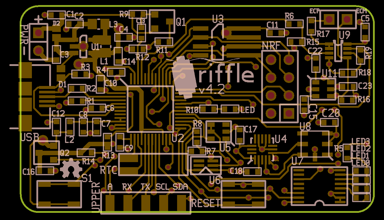
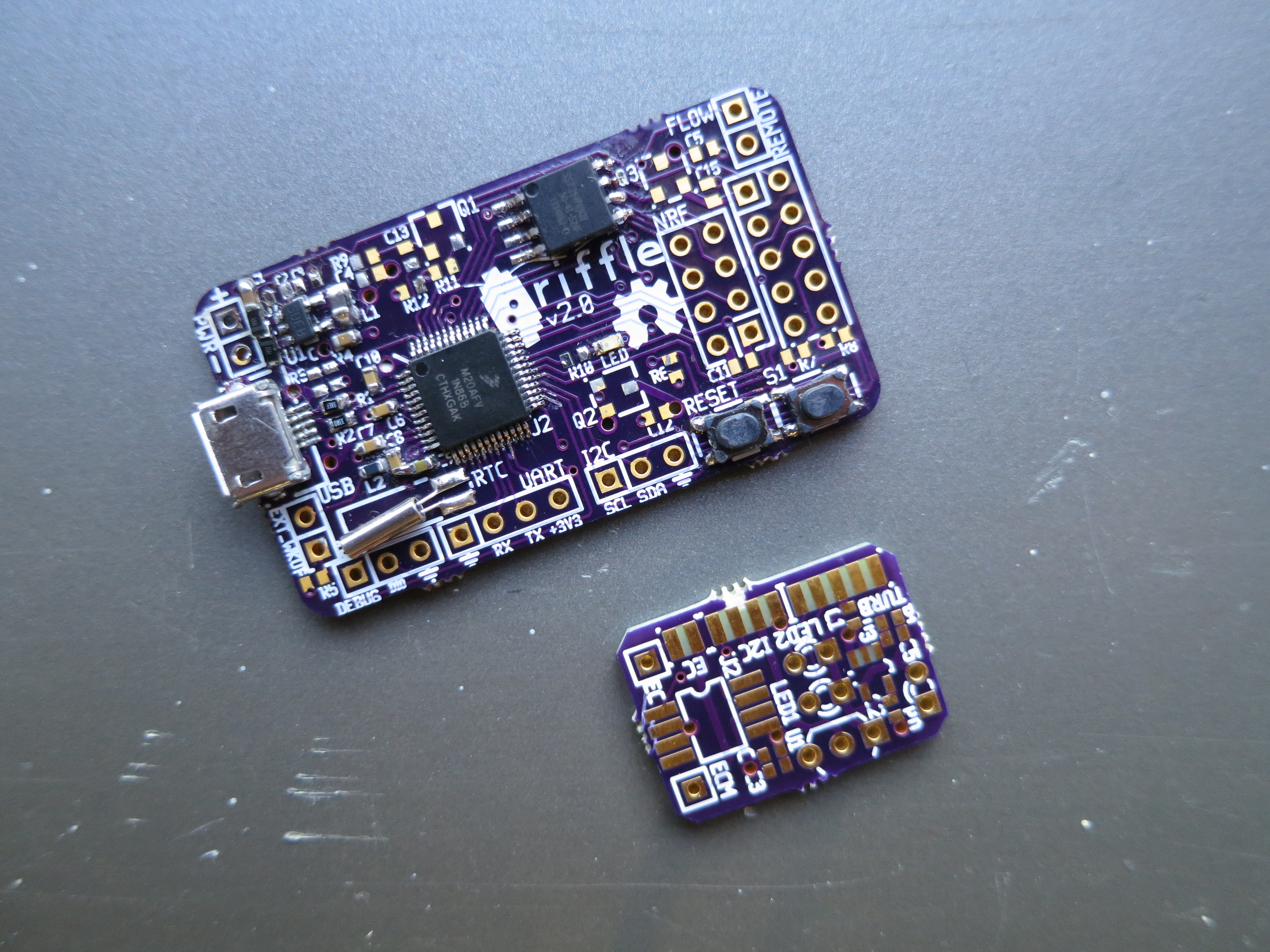 While the McHck utilizes a fully open source toolchain for development, it is not yet compatible with the Arduino IDE, and thus seemed to us to be less accessible to a general audience.
### Atmel328 + FTDI
In parallel, we began developing a circuit board that would be fully compatible with the Arduino IDE, and would have a shape and size appropriate for the most common, 20 mm water bottle mouth diameter. Using a water bottle as an enclosure also meant that most of the sensor pinouts should be located on the 'end' of the board, allowing for cables to pass vertically through the neck of the bottle.
Our first design relied on an external FTDI programmer cable for connecting the device to a laptop for programming or data transfer.:
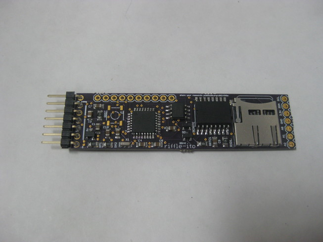
 We decided that this design had the following disadvantages:
- The separate FTDI cable represented 'yet another part to lose' for users, and was more expensive than including a USB-Serial converter chip on the board;
- The pin arrangement, which only allowed for 7 pins at the end of the board, could be enhanced by the addition of an additional row of pins and the use of a 2x7 right-angle connector.
### Atmel328 + CH340g
The latest (as of this writing) version of the [Riffle_328](https://github.com/dwblair/riffle_328) -- Version 0.1.8 -- incorporated these suggested changes to the pinout and USB-Serial, and also included some other changes to power circuitry and component arrangements on the board.

 This version of the Riffle has the current features:
- Programmed as an "UNO" in the Arduino IDE
- Uses an Atmel 328p chip, running at 16 MHz and 3.3V.
- On-board microSD card
- On-board Serial-USB conversion using the CH340 chip.
- Battery measurement circuit
- High-precision, temperature-compensated RTC, the DS3221, with a CR1220 backup battery to maintain the time.
- Two power inputs, 3.5 - 6V. -- one allows for Lithium-Ion charging when the Riffle is plugged into USB, the other is for extended, low-power operation.
- It has additional on-board EEPROM memory, accessible via the I2C bus.
- It has MOSFET switches that can power down the microSD card, the external sensor power, and the battery measurement circuitry.
- Analog pins, Digital pins, Power, Ground, Battery voltage, and I2C and SPI buses are broken out on a 2x7 header at the end of the board, as follows:
# Power and Battery Life
The Riffle is designed to provide the necessary components for a water monitor device in a circuit board design that can last in the field for at least several weeks on a battery.
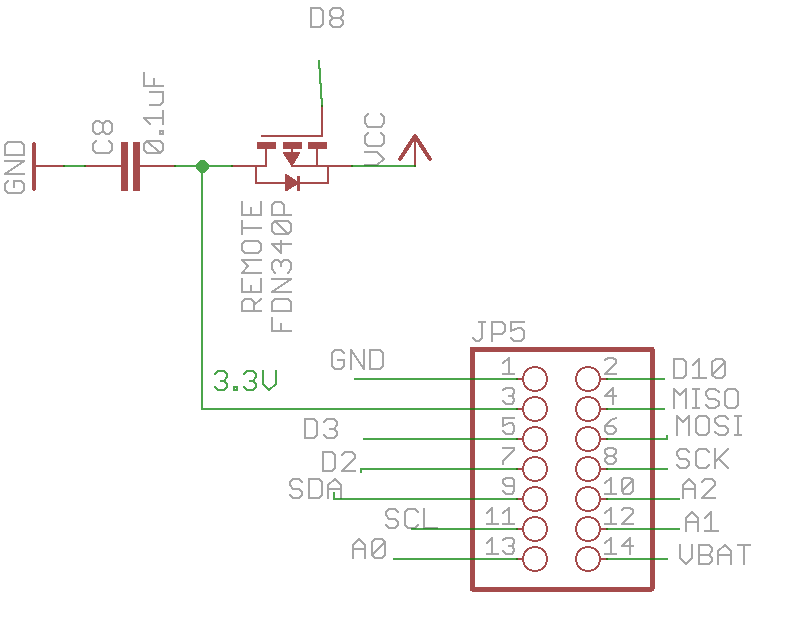
**MOSFET switches.** To this end, on the Riffle_328 ver 0.1.8.0, circuits which aren't needed during 'sleep' mode are controlled by MOSFET switches: external sensors, battery measurement circuitry, and the SD card:
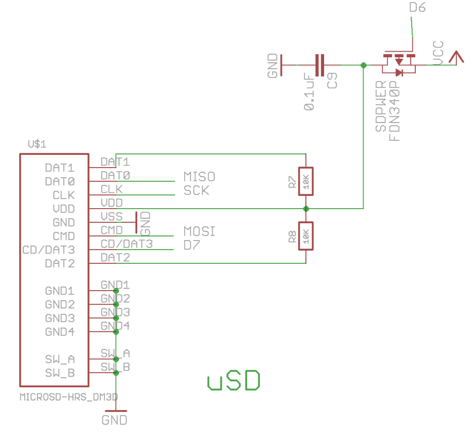
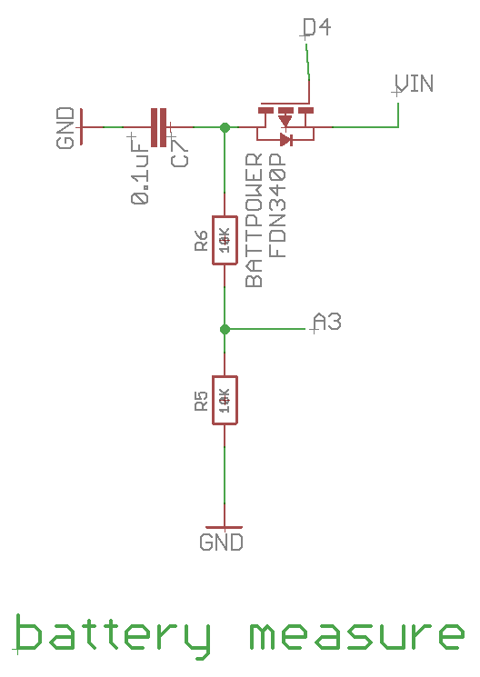
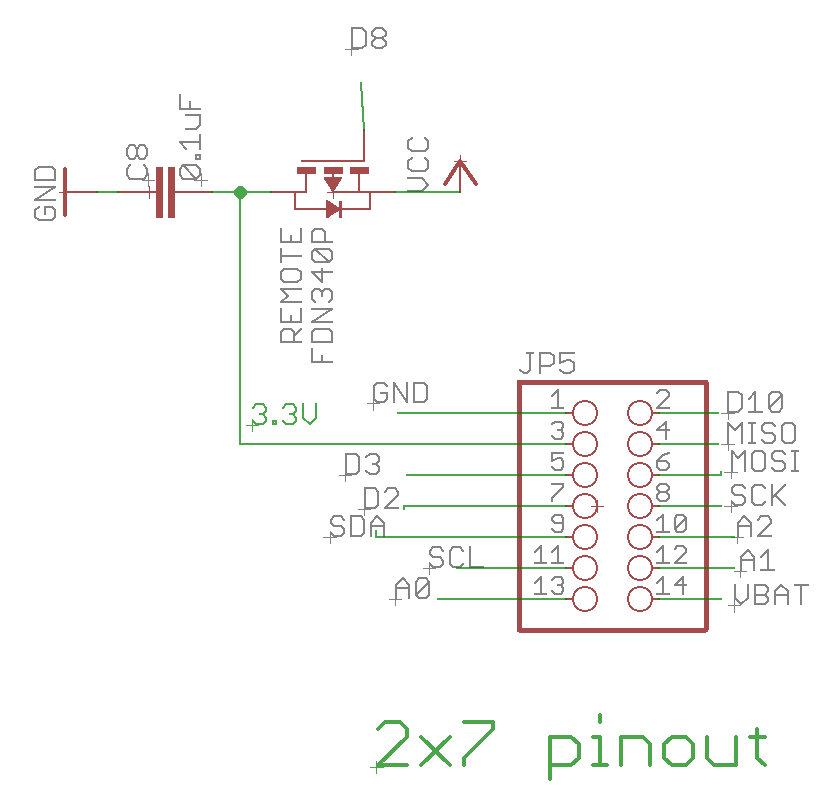 Each of the associated MOSFETS is controlled by a 328p digital pin which is dedicated to controlling that sub-circuit.
In addition to the lowest power sleep currents achievable by the 328p microcontroller chip, other chips on the board introduce their own 'quiescent power' drains.
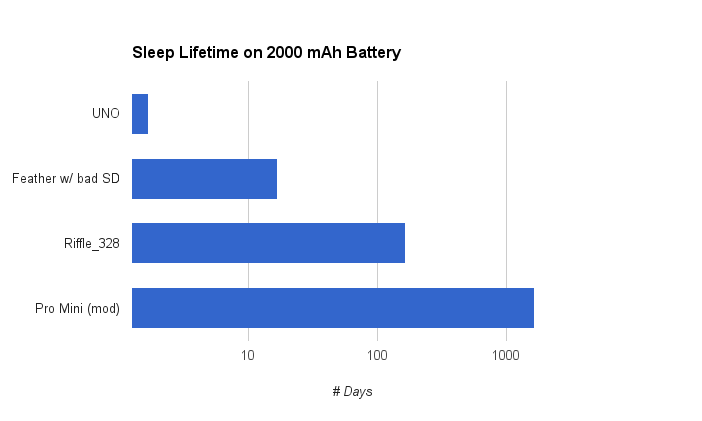
- As a reference, the minimal circuitry associated with an Arduino Pro Mini, with its LED removed in order to further reduce power consumption, results in a sleep mode [as low as 0.05 mA](http://www.home-automation-community.com/arduino-low-power-how-to-run-atmega328p-for-a-year-on-coin-cell-battery/). Because this circuit is close to the bare minimal for a useful microcontroller design compatible with the Arduino IDE, it is informative to compare our design to this standard.
- On the other end of the spectrum and Arduino UNO 'sleeps' at a relatively high current of 45 mA.
- Because SD cards can [vary widely in their sleeping power consumption](https://edwardmallon.wordpress.com/2014/09/22/high-sleep-current-problem-solved/), a datalogger such as the Adafruit Feather which does not have a MOSFET switch for making sure that power is cut to the SD card when not in use can witness sleeping currents as high as 5.0 mA.
- The Riffle, with its MOSFET-controlled SD card circuit, has been measured as using 0.5 mA in sleep mode by Kina Smith, who [developed code](https://publiclab.org/notes/kinasmith/06-14-2016/fixed-riffle-sd-card-power-consumption) for exploiting the SD-turnoff capability.
A common lithum ion battery with a capacity of 2200 mAh is easy to source for $10 (less in bulk), and is ideal for inserting into a 20 mm diameter water bottle mouth. Using 2000 mAh as a reference battery capacity, these various categories of 'sleep lifetime' are plotted below in terms of # of days:
 Further testing is needed to see if the Riffle's current approach to low-power datalogging -- turning off the SD card while sleeping -- is a reliable way of storing data, as it is not the recommended protocol for SD cards.
Some improvements to battery life might be achieved by using the on-board EEPROM memory to buffer data before writing to the SD card. For more discussion on this issues, see [this discussion on Public Lab](https://publiclab.org/notes/kinasmith/06-14-2016/fixed-riffle-sd-card-power-consumption#c15098).
In general, optimizations of sub-circuit designs on the Riffle might be found that would push it further towards the limit suggested by the Arduino MIni Pro limit.
Edward Mallon has posted his extensive invesigations into achieving low power modes with Arduino-based dataloggers [here](https://edwardmallon.wordpress.com/2015/11/05/a-diy-arduino-data-logger-build-instructions-part-4-power-optimization/).
# Sensors and Modularity
The design of the Riffle_328 brought out the important sensor interface pins at one end of the circuit board, in order to allow for use inside water bottles (and other linear containers).
In order to allow for instruments to be designed iteratively, no sensors were included on the board itself; instead, the design is intended to allow for a 'plug-in' modularity to enable sensor development.
In fact, for external boards that only utilize one of the two pin rows, such boards are easily adapted as 'breakout boards' when prototyping on breadboards.
### Protoboard
To facilitate the deployment of prototype circuits with the Riffle, a ['protoboard' plug](https://github.com/OpenWaterProject/riffle_328-proto) in was designed that connects to the 2x7 pinout and breaks out the individual pins:
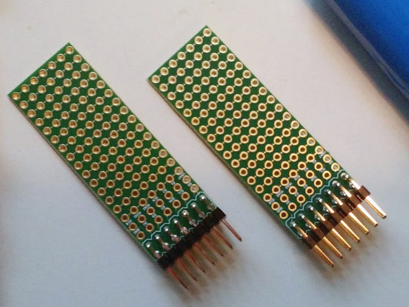 This design makes it relatively easier to move a 'breadboarded' sensor design to the Riffle for deployment.
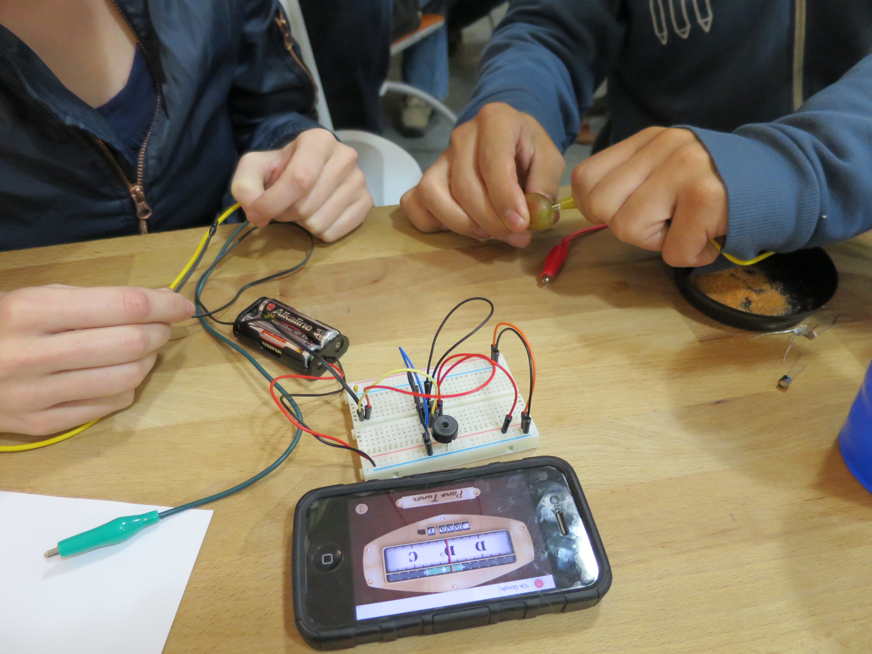
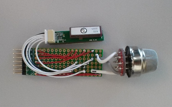 Ultimately, plug-in sensor boards might come out of a workflow in which the sensor is protoyped on a breadboard, implemented on a protoboard and deploymed ... and then, when the circuit design has solidified, a custom PCB can be designed to facilitate circuit assembly:
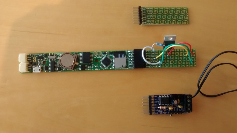 An example of such a circuit design on a RIffle protoboard can be found in the Open Water [riffle_328-turbidity](https://github.com/openwaterproject/riffle_328-turbidity) repository:
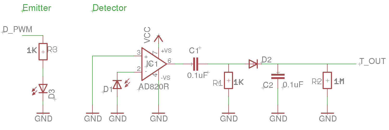
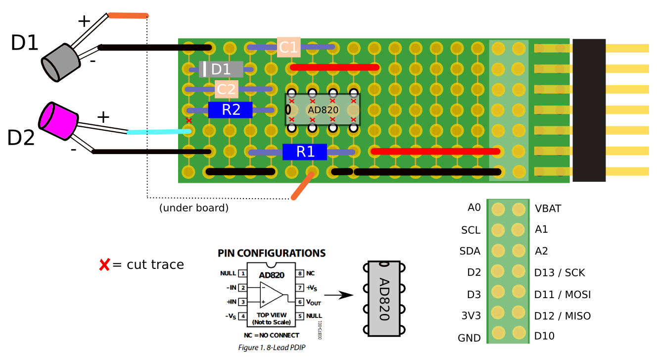 Further instrument designs based on the Riffle protoboard can be found below:
- [riffle_328-depth](https://github.com/OpenWaterProject/riffle_328-depth) -- Depth measurement circuit prototype
- [riffle_328-turbidity](https://github.com/OpenWaterProject/riffle_328-turbidity) -- Turbidity sensor prototype
- [riffle_328-thermistor](https://github.com/OpenWaterProject/riffle_328-thermistor) -- Connecting a thermistor to a Riffle
- [riffle_328-i2c](https://github.com/OpenWaterProject/rriffle_328-depth) -- Connecting i2c sensors to a Riffle
- [riffle_328-one-wire](https://github.com/OpenWaterProject/rriffle_328-one-wire) -- Connecting one-wire sensors to a Riffle
# Storage and Data Retrieval
The Riffle_328 design allows for several modes of data storage and retrieval, some of better-explored than others.
### SD card
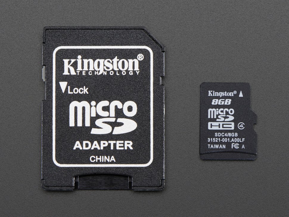
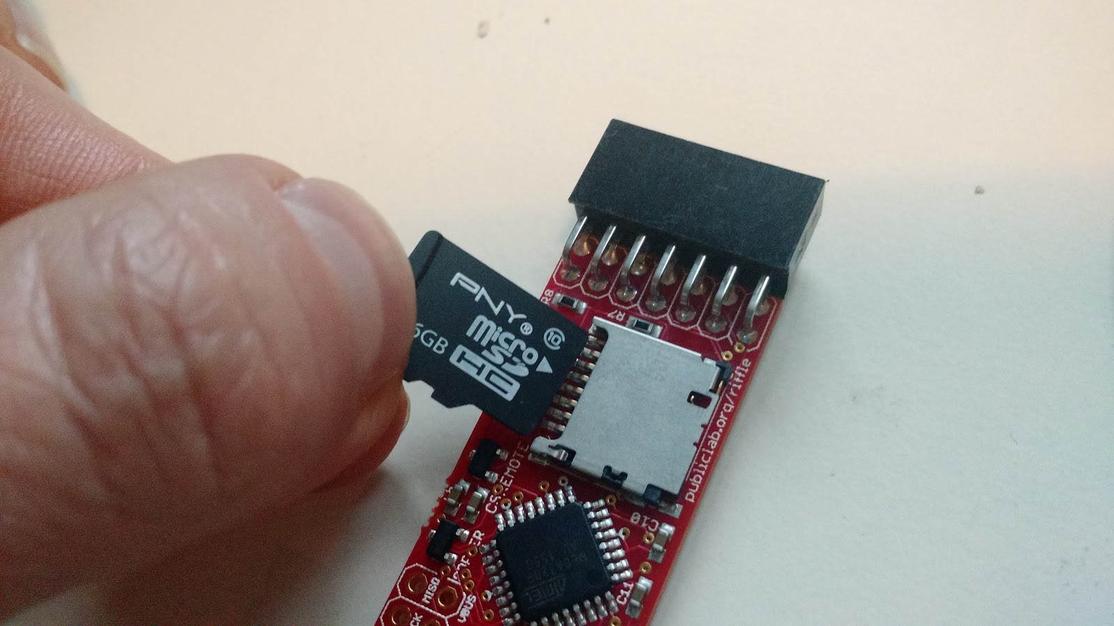
To date, the default mode of data storage and retrieval on the Riffle has been the micro SD card. Typical field sensor data is easily accomodated by the 4 GB+ microSD cards that are available. Code has been developed for the Riffle that allows for data to be recorded to the SD card, and then cuts power to the SD card when it is not in use. Then, the SD card can be plugged into a laptop for data transfer.
It will be important to test the current procedure for cutting power to the SD card, as it has been suggested that this approach may be 'out of spec' for SD cards, and lead to instabilities in reading / writing (and, perhaps, data loss).
 ### eeprom
The Riffle_328 also provides external [EEPROM](https://en.wikipedia.org/wiki/EEPROM) as storage. EEPROM [can provide up to 256Kb of data storage](http://www.hobbytronics.co.uk/arduino-external-eeprom) relatively inexpensively; this amount of data storage is sufficient for many applications.
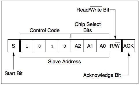 The advantage of EEPROM is that such chips are much more readilly capable of low power consumption when not in use; this capability is part of their design specification, and is possibly more stable than the MOSFET-controlled SD card approach to low-power datalogging.
In addition, EEPROM can be used to store settings (device id, monitoring frequency, sensor settings) that will persist even when if batteries are removed.
### Low-power radio (SPI)
Recently, the focus on "IOT" technologies to enable remote sensor data to be retrieved wirelessly has resulted in the emergence of several low-power radio chips capable of transmitting data for hundreds (in some cases, thousands) of meters, using the low data rates that are perfectly suited to environmental monitoring data.
Some salient examples of such technologies:
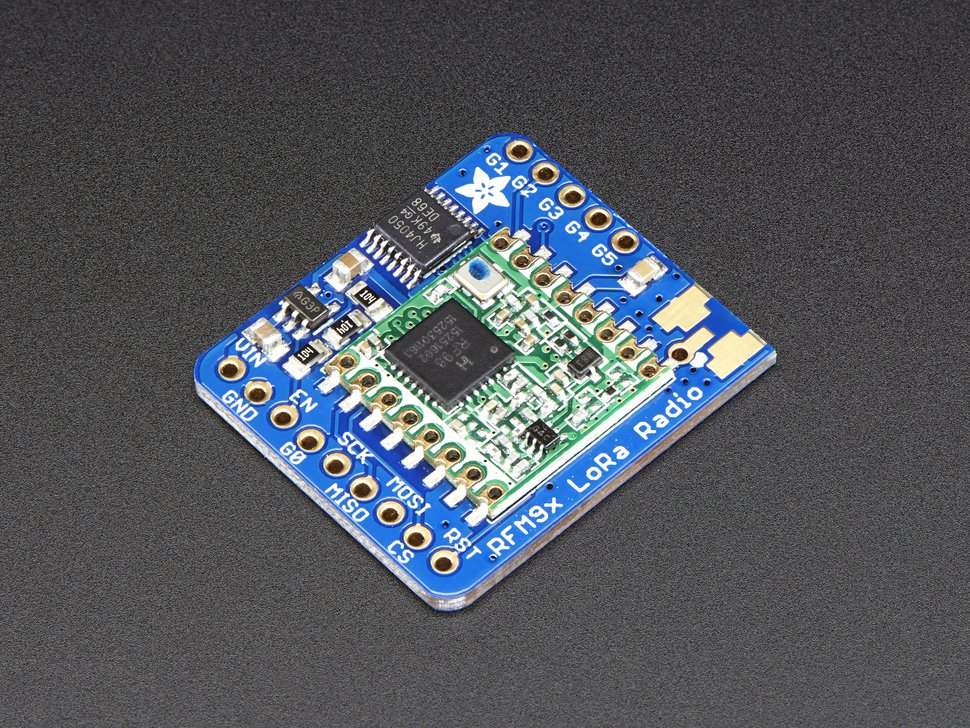
- LoRa radio hardware is capable of transmitting for 1 km + in lightly wooded areas, and for several kilometers line-of sight, with more sophisticated antennae. Typical broadcast frequences are in the 900 MHz or 400 MHz range.
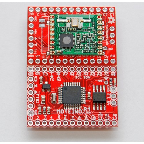
 - RFM69 is another radio protocol and associated hardware design that can typically transmit for hundreds of meters. It has been available to the open source community for longer than the LoRa radios, so more features have been discovered / enabled (mesh networking, encryption, addressing). Typical broadcast frequences are in the 900 MHz or 400 MHz range.
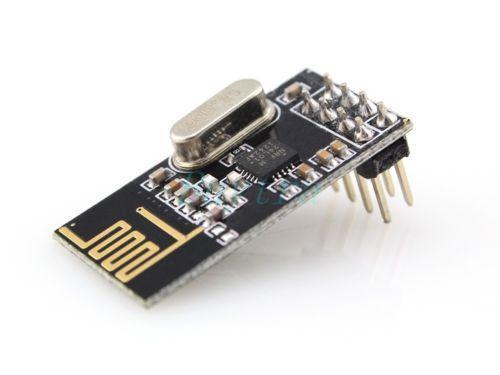
 - The nRF24L01 is a popular low-cost radio, broadcasting at 2.4GHz. The protocol and the frequency spectrum used result in inferior transmission characteristics when compared with LoRa and RFM69 above -- typical distances achieved are under 200 meters line-of-site.
 ### Cell phone (Serial)
GSM technology is now readily accessible by micrcontrollers, with hardware and associated libraries available via Adafruit, Sparkfun, and other manufacturers.
The [Adafruit FONA](https://www.adafruit.com/products/2542?gclid=Cj0KEQjwvIO_BRDt27qG3YX0w4wBEiQAsGu3eZaPCSK_HvwB_g1sdkQUe2VRHXXs-Yz9d59K5Msxg8waAihM8P8HAQ) has now been used with the Riffle:
- in Colombia in collaboration with the University of Los Andes for the ['Surata Visible'](https://publiclab.org/notes/donblair/10-19-2015/surata-visible-part-i) project, in which Riffle monitors were set up in the Bucaramanga region
- in West Virginia by John Keefe for his [West Virgingia State University Sensor Journalism class](http://johnkeefe.net/monitoring-the-monongahela).
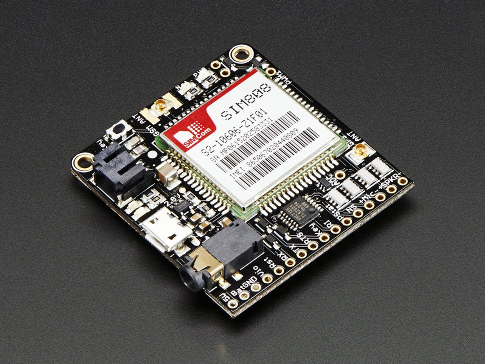
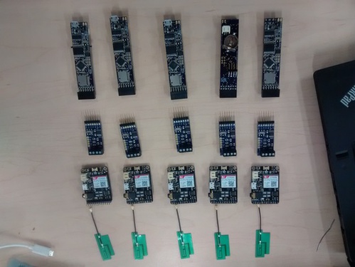 These GSM modems can be controlled directly by the Riffle, and can be set to 'sleep' when not in use. The advantage of using them is enhanced network coverage (anywhere that the SIM card provider has coverage); the disadvantage is continuing fees for data transfer (typically, monthly data usage associated with the SIM card).
### Audio
From nearly the beginning of the Riffle project, audio has been considered as an accessible data transfer format.
The [Coqui](https://publiclab.org/wiki/coqui), which began as a conductivity sensor design circuit for the Riffle, involved a measurement technique that, as a by-product, generates a frequency that can be constrained to the human-audible range. While that particular conductivity circuit is no longer considered viable for stable measurements of conductivity by the Riffle, the basic idea of conveying changes in a parameter via changes in pitch remains an appealing mode of accessible sensor 'readout'.
More recently the development of the ['WebJack'](https://github.com/publiclab/webjack) audio modem system for transferring data between microcontrollers and computers via the WebRTC interface has provided a promising digital audio avenue for transferring data between the Riffle and any computing platform with a suitable browser.
Early on, the idea of conveying sensor data via voicemail [was explored](https://publiclab.org/notes/donblair/09-10-2014/water-quality-coqui-voicemails). Sensor data in which data was represented by continuous changes in pitch, as with the Coqui, proved problematic, as these constant 'whine' frequencies seemed to be filtered out by telephony systems. The SoftModem FSK protcol used by WebJack may be capable of avoiding such filtering. Already, data has been successfully 'read off' a YouTube video of WebJack data.
# Pinouts and Bus Interfaces
The Riffle_328 has its digital and analog interface pins located at one end of the board, arranged as follows:
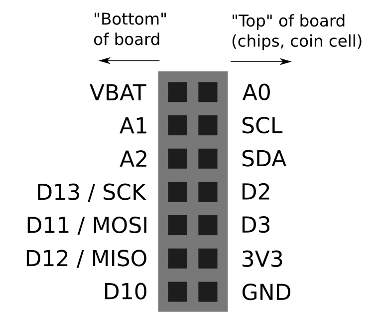
 The pins used were selected based on their ability to enable interfacing with several common protocols / modes of connecting to external electronics. These modes can usefully be broken down into the following categories:
### Analog and digital pins
- A0, A1, A2: 10 bit ADC
- D2, D3: timer / interrupts
- D11, D12, D13: SPI
- SCl, SDA: I2C
- D10: digital pin
- VBAT: the raw battery voltage coming into the board
### i2c
Many sensors now use the [i2c](https://en.wikipedia.org/wiki/I%C2%B2C) interface. It's a convenient way of sharing several devices on the same bus. All devices on the i2c bus require only four lines -- the dedicated SDA and SCL lines, Power (3.3V for the Riffle), and GND.
The BMP180, a pressure and temperature sensor, is an example of a common, inexpensive i2c chip that is easy to connect to the Riffle.
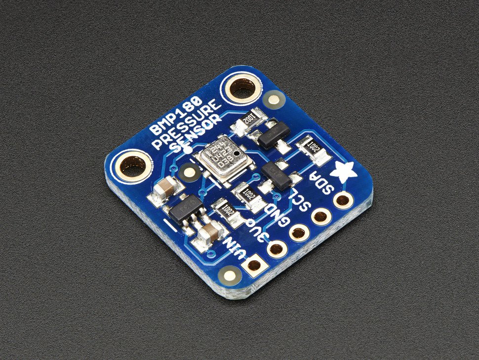 On the Riffle itself, the RTC chip and the EEPROM chip are themselves i2c devices. For this reason, i2c pullups are already included on the Riffle board itself. Usually, additional pullups on the i2c lines in external breakout boards shouldn't interfere with i2c signalling.
### SPI
Like i2c, [SPI](https://en.wikipedia.org/wiki/Serial_Peripheral_Interface_Bus) is a also a bus interface, but is optimized for higher data transfer rates. The bus line requires more pins -- MISO, MOSI, and SCK, as well as PWR and GND -- and also necessitates running an additional signal line to every chip on the SPI bus that would like to communicate with the microcontroller. While this means that pins can quickly run out when being alloted for multiple SPI devices on the same bus, SPI provides an advantage when sending high-speed signals to devices on the board -- in effect, dedicated signal line means that addressing collisions are less likely. This interface has been used in several low-power radio devices, including the LoRa, RFM69, and Nordic radio chips listed above. The SPI interface was brought out at the end of the 2x7 Riffle header specifically to allow for connecting to low power SPI radio modules such as these.
### RX / TX
The UART interface of the 328p is broken out on the bottom of the board in case it's useful for particular applications (for GPS or talking directly to another microcontroller over serial). Often, UART can be emulated using other pins ('Soft Serial'); but some libraries require the use of the 328 dedicated 'hardware' UART.
# Data Analysis
The RIffle is useless as a water monitor if the data captured by it isn't readily transferred to devices that can be used to plot, analyze, and disseminate the data.
### CSV or TSV as standard formats
The feedback we have received from discussions with hydrologists and others who regularly make use of datalogger devices is that there exists a variety of different 'data workflows' and associated software tools in current use. Most of the practitioners we spoke with therefore suggested that the most useful approach would be to use a common data format like 'CSV' (comma-separated values) or 'TSV' (tab-separated values) when storing data; the rest of the data analysis toolchain would then be up to the user.
### Spreadsheet software
We have, however, envisioned demonstrating easy workflows using commonly-used spreadsheet software like Excel or Google Docs, so that those who are new to water monitoring can easily upload their data and begin to analyze it.
 ### Jupyter
Recently, Jupyter has emerged as an open source web-based platform enabling easily-shared analyses in Python, R, and a host of other computing languages.

 In the future, we would like to demonstrate the use of Jupyter notebooks for analyzing Riffle data collected from the field.
# Development Workflow
A large part of our approach to the design of the Riffle has involved an attempt to enable an iterative, collaborative sensor design and deployment process.
Enabling such a process also requires a thoughtful approach to the *archiving* of hardware and software associated with the datalogger and sensor designs.
We are hoping to model an open hardware approach that uses the infrastructure of software repositories -- in our example, Github -- to support a community around distributing, 'forking', and 'merging' hardware and software features, and facilitating the process of documentation.
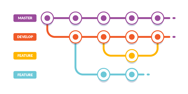 In general, we envision that compatible, coherent hardware and software designs will be strictly [version-controlled](https://github.com/dwblair/riffle_328) so that those who seek to replicate and use particular designs can find all of the necessary information in one, stable location.
Meanwhile, information and documentation that has been gathered about the use of such tools, as well as collections of various tools appropriate to particular use-cases, can be hosted using infrastructure that better facilities community dialogue and curation, such as the [Publiclab.org](http://publiclab.org) website.
 - Identifying and locating point sources of pollution along water bodies like rivers and streams;
- Monitoring the water height and water quality in remote wells;
- Assesing the impact of farming on bays and lakes;
- Many other related applications.
As a hydrologist, Mark has used various water monitoring technologies in his research for many years. Mark was interested in the possible use of 'open source hardware' in water monitoring, and identified for us some of the main challenges presented by the current, dominant commercial designs:
- **Proprietary data format.** Most commercial systems record data in an encrypted format that can only be decoded by their proprietary software.
- **Proprietary software suite.** The software required to interact with the hardware is itself proprietary and 'closed'; only the company selling the software is capable of improving the software or fixing bugs, and often the development cycle is slow.
 - **Proprietary hardware.** Typical commercial water monitoring hardware requires special hardware dongles' in order to retrieve data from the device. The monitoring hardware itself is often of high quality, but modifications or the additional of external sensors is not allowed or supported.

 Around the same time, Chris Fastie, a forest ecologist familiar with the use of dataloggers in forestry research, wrote up an [assessment] of the qualities that an open source datalogger might usefully have in order to provide a useful alternative to current commercial solutions.
In general, the impression emerged that while solid, thoughtfully engineered monitoring solutions exist, they typically are not designed to allow for modification, innovation, interoperability, or easy data sharing.
# Project Goals
As a result, we decided to begin a project to develop an 'open hardware water monitor', useful for some common water monitoring applications. We sought to make something which would have the following characteristics:
- **Low power**. Capable of monitoring at a remote locations for many days -- weeks, at least -- on a battery.
- **Open source hardware.** We hoped to leverage the world of open source hardware electronics, and see if we could build a basic water monitor device that allowed for easy hardware modification and reprogramming, and easy for people to add new sensors.
- **Open source software.** We aimed to develop simple ways of transferring, visualizing, and analyzing the data collected by these monitors.
- **Open and accessible data formats.** We also planned to design the device so that it could output data in a common data format (CSV), using accessible data storage media (SD cards).
- **Accessible materials.** The water monitor would require a waterproof enclosure -- our aim to was to construct this enclosure, to the extent that was practical, from materials that could be sourced / replaced locally, in order to reduce costs and enhance accessibility. The circuit design should use components and a process that would be easy for others to replicate themselves.
- **Encouirage a large community of users.** Our hope, too, was to establish a community around such a device, so that hardware users could support one another's efforts, help debug code, and share new designs.
# Overview of Design Parameters
Below, we describe the main components of the Riffle design, broken up into categories. While some of these categories have inherent overlap -- for example, the circuit board design is intimately related to the choice of enclosure shape -- this division seems to provide a useful way of seaprating out tractable components of the design problem we are attempting to address:
[**Enclosure**](#enclosure). The container for the water monitoring electronics.
[**Circuit Board Design**](#circuit-board-design). Design considerations around the 'printed circuit board' at the heart of the water monitor.
[**Power and Battery life**](#power-and-battery-life). Choices made in order to reduce power consumption on the device, in order to enable extended monitoring in the field.
[**Sensors and Modularity**](#sensors-and-modularity). Choices made about the enclosure and circuit board design in order to allow for the main sensing applications of interest.
[**Storage and Data Retrieval**](#storage-and-data-retrieval). The various mechanism in the Riffle design for data storage and the associated modes of data retrival.
[**Pinouts and Bus Interfaces**](#pinouts-and-bus-interfaces). The electronic inputs and outputs afforded by the circuit board design, some of which are associated with specific, common bus protocols used by common sensors.
[**Data Analysis**](#data-analysis). Considerations for making analysis of the data acquired by open hardware water mointors easier to analyze and share.
[**Development Workflow**](#development-workflow). The workflow we envisage around curated designs, code, and data on Public Lab and Github.
[**Similar Projects and Future Directions**](#similar-projects-and-future-directions). A brief listing of projects with similar goals, and possible next steps for Riffle development.
Each of these categories is elaborated upon more fully, below.
------------------
# Enclosure
One of the first discussions around the water monitoring design was: **how will we make the electronics waterproof?** All of the commercial solutions involve fully custom enclosures, usually made from (initially) expensive metal or plastic molds. In contrast, we hoped to enable users of our design to source their own enclosure parts locally -- both to reduce cost, and allow for easy modifications / extensions / variants of enclosure designs, associated with novel applications.
The two main enclosure designs that presented themselves used:
- **PVC**; and
- commonly-available **water bottles**.
### PVC
PVC pipe is used around the world for transporting liquids; it is inexpensive, and widely available. It is also already used extensively in hydrology and other fields as a structure for enclosing water monitoring devices (as a sort of 'secondary' enclosure that secures a commercial water monitor in place, and/or controls the flow of water over the water monitor sensor surfaces).
 This material was thus an obvious first choice for the RIffle enclosure. Our initial approach was to identify the minimal set of PVC hardware that would:
- protect the sensitive monitoring electronics
- allow for sensor hardware to be mounted externally, and communicate through the enclosure to the datalogger
- allow easy access to the internal compartment such that the container could be reused between servicing / battery replacement.
We found such a minimal enclosure at our local hardware store, consisting of two screw end-caps and a connecting middle piece.

 The basic idea was then that the main datalogger electronics would sit inside the waterpoof enclosure; and we would 3D print a custom 'endcap' that would fit around the end of the PVC and house the sensor electronics.
 The 3D printed end-cap was designed in OpenSCAD.

 The associated electronics was held in place and sealed by potting it with epoxy.
 We found that this design had several issues:
- The 3D printed material was not easy to make consistently waterproof. Efforts to use epoxy to seal the 3D printed cap were unsuccessful.
- The dimensions of the PVC end-cap fluctuated significantly, so that the 3D printed part did not always connect nicely without extensive modification.
- Sealing the expoxy (the one we were using) seemed difficult without a careful 'baking out' process, which seemed to result an a relatively inaccessible design.
### Mallon enclosure
Subsequently, we have noticed that Edward Mallon has developed a [much more elegant PVC enclosure approach](https://edwardmallon.wordpress.com/2015/02/04/a-new-diy-underwater-housing-for-2015/), involving PVC parts that maintain a watertight seal through a 'gasket' and -ring configuration, so that accessing the internal electronics to change a battery and resealing the device become much easier:

 This design seems to be a robust PVC enclosure (Mallon's design has lasted several months underwater), with parts that are accessible online; the end-cap arrangment allows for sensor modules to be mounted in an accessible 'platform' configuration.
### Bottle
After having trouble sealing our PVC enclosure and coming up with a good way of connecting our datalogger to external sensors, we happened upon the idea of containing the electronics in commonly-used plastic water bottles.


 This design idea seemed to offer the following advantages:
- The enclsoure was readily sourced nearly anyhwere in the world
- It would be a compelling ['detrivore'](https://publiclab.org/wiki/detritivore-design-by-mathew-lippincott) reuse of waste materials
- The enclsoure was likely easy to seal successfully
- Key applications of the monitor -- measuring temperature and conductivity -- might be accomplished by simply sticking probes through the water bottle cap.
Several variations on this water bottle enclosure were then developed. Some of the ideas explored were:
- Using rice or mineral oil to protect the electronics against water leaks or water pressure
 - Using screws through the bottle cap to monitor conductivity:


 - Using a rubber stopper in lieu of a plastic bottle cap, in order to create a 'gasket' seal and allow for wires and other sensor materials to be sealed into an opening more readily:
 - [Custom water bottle caps](https://publiclab.org/notes/mathew/01-16-2015/sketching-a-waterproof-pop-bottle-sensor-system) that could house sensors and affix them to the end of the bottle securely.
- Various [other ideas](https://publiclab.org/notes/mathew/02-26-2015/sensors-in-soda-bottles).
The water bottle approach was used in John Keefe's ['sensor journalism' deployment](http://johnkeefe.net/monitoring-the-monongahela) in West Virginia with good success, resulting in several-week deployments of sensors underwater.
 The shape of the water bottle also allowed for anchoring a weight to it fairly easily in order to keep it below water:
 ### Other
In the course of Riffle development in the Public Lab community, other enclosure ideas of been proposed.
**Nalgene bottles.** Chris Fastie focused on a [Nalgene-based design](https://publiclab.org/notes/cfastie/05-27-2016/riffle-campout). The larger size of the Nalgene bottle mouth allows for the use of a standard AA battery enclosure, and makes it relatively easy to create multiple pass-throughs:


 **3D printed enclosures**. Rebeccah [posted a design](https://publiclab.org/notes/rebeccah/08-29-2016/riffle-device-water-conductivity-sensor) for a 3D printed enclosure that contained compartments for both the RIffle and a lithium ion battery; it also has recesses for magnets to keep the enclosure shut:

 Several other designs are likely possible. We're eager to see further novel enclosure designs developed, tailored to particular applications and leveraging locally-available materials.
# Circuit Board Design
### Initial inspiration: MCHCK
 The first Riffle design by Ben Gamari and Laura Dietz leveraged an open source microcontroller design, the [McHck](https://mchck.org/). The McHck, designed around the same Freescale MK20DX32VLF5 ARM chip as one of the more recent [Teensy](https://www.pjrc.com/teensy/) boards, has:
- built-in USB
- a footprint for an nRF24L01 radio
- up to 8Mbit flash memory
- LDO, buck and boost power management circuitry options.
A datalogger design based on the McHck that adds an SD card and novel pinouts can be found in [Ben Gamari's Github repo](https://github.com/bgamari/riffle).

 While the McHck utilizes a fully open source toolchain for development, it is not yet compatible with the Arduino IDE, and thus seemed to us to be less accessible to a general audience.
### Atmel328 + FTDI
In parallel, we began developing a circuit board that would be fully compatible with the Arduino IDE, and would have a shape and size appropriate for the most common, 20 mm water bottle mouth diameter. Using a water bottle as an enclosure also meant that most of the sensor pinouts should be located on the 'end' of the board, allowing for cables to pass vertically through the neck of the bottle.
Our first design relied on an external FTDI programmer cable for connecting the device to a laptop for programming or data transfer.:

 We decided that this design had the following disadvantages:
- The separate FTDI cable represented 'yet another part to lose' for users, and was more expensive than including a USB-Serial converter chip on the board;
- The pin arrangement, which only allowed for 7 pins at the end of the board, could be enhanced by the addition of an additional row of pins and the use of a 2x7 right-angle connector.
### Atmel328 + CH340g
The latest (as of this writing) version of the [Riffle_328](https://github.com/dwblair/riffle_328) -- Version 0.1.8 -- incorporated these suggested changes to the pinout and USB-Serial, and also included some other changes to power circuitry and component arrangements on the board.

 This version of the Riffle has the current features:
- Programmed as an "UNO" in the Arduino IDE
- Uses an Atmel 328p chip, running at 16 MHz and 3.3V.
- On-board microSD card
- On-board Serial-USB conversion using the CH340 chip.
- Battery measurement circuit
- High-precision, temperature-compensated RTC, the DS3221, with a CR1220 backup battery to maintain the time.
- Two power inputs, 3.5 - 6V. -- one allows for Lithium-Ion charging when the Riffle is plugged into USB, the other is for extended, low-power operation.
- It has additional on-board EEPROM memory, accessible via the I2C bus.
- It has MOSFET switches that can power down the microSD card, the external sensor power, and the battery measurement circuitry.
- Analog pins, Digital pins, Power, Ground, Battery voltage, and I2C and SPI buses are broken out on a 2x7 header at the end of the board, as follows:
# Power and Battery Life
The Riffle is designed to provide the necessary components for a water monitor device in a circuit board design that can last in the field for at least several weeks on a battery.
**MOSFET switches.** To this end, on the Riffle_328 ver 0.1.8.0, circuits which aren't needed during 'sleep' mode are controlled by MOSFET switches: external sensors, battery measurement circuitry, and the SD card:


 Each of the associated MOSFETS is controlled by a 328p digital pin which is dedicated to controlling that sub-circuit.
In addition to the lowest power sleep currents achievable by the 328p microcontroller chip, other chips on the board introduce their own 'quiescent power' drains.
- As a reference, the minimal circuitry associated with an Arduino Pro Mini, with its LED removed in order to further reduce power consumption, results in a sleep mode [as low as 0.05 mA](http://www.home-automation-community.com/arduino-low-power-how-to-run-atmega328p-for-a-year-on-coin-cell-battery/). Because this circuit is close to the bare minimal for a useful microcontroller design compatible with the Arduino IDE, it is informative to compare our design to this standard.
- On the other end of the spectrum and Arduino UNO 'sleeps' at a relatively high current of 45 mA.
- Because SD cards can [vary widely in their sleeping power consumption](https://edwardmallon.wordpress.com/2014/09/22/high-sleep-current-problem-solved/), a datalogger such as the Adafruit Feather which does not have a MOSFET switch for making sure that power is cut to the SD card when not in use can witness sleeping currents as high as 5.0 mA.
- The Riffle, with its MOSFET-controlled SD card circuit, has been measured as using 0.5 mA in sleep mode by Kina Smith, who [developed code](https://publiclab.org/notes/kinasmith/06-14-2016/fixed-riffle-sd-card-power-consumption) for exploiting the SD-turnoff capability.
A common lithum ion battery with a capacity of 2200 mAh is easy to source for $10 (less in bulk), and is ideal for inserting into a 20 mm diameter water bottle mouth. Using 2000 mAh as a reference battery capacity, these various categories of 'sleep lifetime' are plotted below in terms of # of days:
 Further testing is needed to see if the Riffle's current approach to low-power datalogging -- turning off the SD card while sleeping -- is a reliable way of storing data, as it is not the recommended protocol for SD cards.
Some improvements to battery life might be achieved by using the on-board EEPROM memory to buffer data before writing to the SD card. For more discussion on this issues, see [this discussion on Public Lab](https://publiclab.org/notes/kinasmith/06-14-2016/fixed-riffle-sd-card-power-consumption#c15098).
In general, optimizations of sub-circuit designs on the Riffle might be found that would push it further towards the limit suggested by the Arduino MIni Pro limit.
Edward Mallon has posted his extensive invesigations into achieving low power modes with Arduino-based dataloggers [here](https://edwardmallon.wordpress.com/2015/11/05/a-diy-arduino-data-logger-build-instructions-part-4-power-optimization/).
# Sensors and Modularity
The design of the Riffle_328 brought out the important sensor interface pins at one end of the circuit board, in order to allow for use inside water bottles (and other linear containers).
In order to allow for instruments to be designed iteratively, no sensors were included on the board itself; instead, the design is intended to allow for a 'plug-in' modularity to enable sensor development.
In fact, for external boards that only utilize one of the two pin rows, such boards are easily adapted as 'breakout boards' when prototyping on breadboards.
### Protoboard
To facilitate the deployment of prototype circuits with the Riffle, a ['protoboard' plug](https://github.com/OpenWaterProject/riffle_328-proto) in was designed that connects to the 2x7 pinout and breaks out the individual pins:
 This design makes it relatively easier to move a 'breadboarded' sensor design to the Riffle for deployment.

 Ultimately, plug-in sensor boards might come out of a workflow in which the sensor is protoyped on a breadboard, implemented on a protoboard and deploymed ... and then, when the circuit design has solidified, a custom PCB can be designed to facilitate circuit assembly:
 An example of such a circuit design on a RIffle protoboard can be found in the Open Water [riffle_328-turbidity](https://github.com/openwaterproject/riffle_328-turbidity) repository:

 Further instrument designs based on the Riffle protoboard can be found below:
- [riffle_328-depth](https://github.com/OpenWaterProject/riffle_328-depth) -- Depth measurement circuit prototype
- [riffle_328-turbidity](https://github.com/OpenWaterProject/riffle_328-turbidity) -- Turbidity sensor prototype
- [riffle_328-thermistor](https://github.com/OpenWaterProject/riffle_328-thermistor) -- Connecting a thermistor to a Riffle
- [riffle_328-i2c](https://github.com/OpenWaterProject/rriffle_328-depth) -- Connecting i2c sensors to a Riffle
- [riffle_328-one-wire](https://github.com/OpenWaterProject/rriffle_328-one-wire) -- Connecting one-wire sensors to a Riffle
# Storage and Data Retrieval
The Riffle_328 design allows for several modes of data storage and retrieval, some of better-explored than others.
### SD card
To date, the default mode of data storage and retrieval on the Riffle has been the micro SD card. Typical field sensor data is easily accomodated by the 4 GB+ microSD cards that are available. Code has been developed for the Riffle that allows for data to be recorded to the SD card, and then cuts power to the SD card when it is not in use. Then, the SD card can be plugged into a laptop for data transfer.
It will be important to test the current procedure for cutting power to the SD card, as it has been suggested that this approach may be 'out of spec' for SD cards, and lead to instabilities in reading / writing (and, perhaps, data loss).

 ### eeprom
The Riffle_328 also provides external [EEPROM](https://en.wikipedia.org/wiki/EEPROM) as storage. EEPROM [can provide up to 256Kb of data storage](http://www.hobbytronics.co.uk/arduino-external-eeprom) relatively inexpensively; this amount of data storage is sufficient for many applications.
 The advantage of EEPROM is that such chips are much more readilly capable of low power consumption when not in use; this capability is part of their design specification, and is possibly more stable than the MOSFET-controlled SD card approach to low-power datalogging.
In addition, EEPROM can be used to store settings (device id, monitoring frequency, sensor settings) that will persist even when if batteries are removed.
### Low-power radio (SPI)
Recently, the focus on "IOT" technologies to enable remote sensor data to be retrieved wirelessly has resulted in the emergence of several low-power radio chips capable of transmitting data for hundreds (in some cases, thousands) of meters, using the low data rates that are perfectly suited to environmental monitoring data.
Some salient examples of such technologies:
- LoRa radio hardware is capable of transmitting for 1 km + in lightly wooded areas, and for several kilometers line-of sight, with more sophisticated antennae. Typical broadcast frequences are in the 900 MHz or 400 MHz range.
 - RFM69 is another radio protocol and associated hardware design that can typically transmit for hundreds of meters. It has been available to the open source community for longer than the LoRa radios, so more features have been discovered / enabled (mesh networking, encryption, addressing). Typical broadcast frequences are in the 900 MHz or 400 MHz range.
 - The nRF24L01 is a popular low-cost radio, broadcasting at 2.4GHz. The protocol and the frequency spectrum used result in inferior transmission characteristics when compared with LoRa and RFM69 above -- typical distances achieved are under 200 meters line-of-site.
 ### Cell phone (Serial)
GSM technology is now readily accessible by micrcontrollers, with hardware and associated libraries available via Adafruit, Sparkfun, and other manufacturers.
The [Adafruit FONA](https://www.adafruit.com/products/2542?gclid=Cj0KEQjwvIO_BRDt27qG3YX0w4wBEiQAsGu3eZaPCSK_HvwB_g1sdkQUe2VRHXXs-Yz9d59K5Msxg8waAihM8P8HAQ) has now been used with the Riffle:
- in Colombia in collaboration with the University of Los Andes for the ['Surata Visible'](https://publiclab.org/notes/donblair/10-19-2015/surata-visible-part-i) project, in which Riffle monitors were set up in the Bucaramanga region
- in West Virginia by John Keefe for his [West Virgingia State University Sensor Journalism class](http://johnkeefe.net/monitoring-the-monongahela).


 These GSM modems can be controlled directly by the Riffle, and can be set to 'sleep' when not in use. The advantage of using them is enhanced network coverage (anywhere that the SIM card provider has coverage); the disadvantage is continuing fees for data transfer (typically, monthly data usage associated with the SIM card).
### Audio
From nearly the beginning of the Riffle project, audio has been considered as an accessible data transfer format.
The [Coqui](https://publiclab.org/wiki/coqui), which began as a conductivity sensor design circuit for the Riffle, involved a measurement technique that, as a by-product, generates a frequency that can be constrained to the human-audible range. While that particular conductivity circuit is no longer considered viable for stable measurements of conductivity by the Riffle, the basic idea of conveying changes in a parameter via changes in pitch remains an appealing mode of accessible sensor 'readout'.
More recently the development of the ['WebJack'](https://github.com/publiclab/webjack) audio modem system for transferring data between microcontrollers and computers via the WebRTC interface has provided a promising digital audio avenue for transferring data between the Riffle and any computing platform with a suitable browser.
Early on, the idea of conveying sensor data via voicemail [was explored](https://publiclab.org/notes/donblair/09-10-2014/water-quality-coqui-voicemails). Sensor data in which data was represented by continuous changes in pitch, as with the Coqui, proved problematic, as these constant 'whine' frequencies seemed to be filtered out by telephony systems. The SoftModem FSK protcol used by WebJack may be capable of avoiding such filtering. Already, data has been successfully 'read off' a YouTube video of WebJack data.
# Pinouts and Bus Interfaces
The Riffle_328 has its digital and analog interface pins located at one end of the board, arranged as follows:

 The pins used were selected based on their ability to enable interfacing with several common protocols / modes of connecting to external electronics. These modes can usefully be broken down into the following categories:
### Analog and digital pins
- A0, A1, A2: 10 bit ADC
- D2, D3: timer / interrupts
- D11, D12, D13: SPI
- SCl, SDA: I2C
- D10: digital pin
- VBAT: the raw battery voltage coming into the board
### i2c
Many sensors now use the [i2c](https://en.wikipedia.org/wiki/I%C2%B2C) interface. It's a convenient way of sharing several devices on the same bus. All devices on the i2c bus require only four lines -- the dedicated SDA and SCL lines, Power (3.3V for the Riffle), and GND.
The BMP180, a pressure and temperature sensor, is an example of a common, inexpensive i2c chip that is easy to connect to the Riffle.
 On the Riffle itself, the RTC chip and the EEPROM chip are themselves i2c devices. For this reason, i2c pullups are already included on the Riffle board itself. Usually, additional pullups on the i2c lines in external breakout boards shouldn't interfere with i2c signalling.
### SPI
Like i2c, [SPI](https://en.wikipedia.org/wiki/Serial_Peripheral_Interface_Bus) is a also a bus interface, but is optimized for higher data transfer rates. The bus line requires more pins -- MISO, MOSI, and SCK, as well as PWR and GND -- and also necessitates running an additional signal line to every chip on the SPI bus that would like to communicate with the microcontroller. While this means that pins can quickly run out when being alloted for multiple SPI devices on the same bus, SPI provides an advantage when sending high-speed signals to devices on the board -- in effect, dedicated signal line means that addressing collisions are less likely. This interface has been used in several low-power radio devices, including the LoRa, RFM69, and Nordic radio chips listed above. The SPI interface was brought out at the end of the 2x7 Riffle header specifically to allow for connecting to low power SPI radio modules such as these.
### RX / TX
The UART interface of the 328p is broken out on the bottom of the board in case it's useful for particular applications (for GPS or talking directly to another microcontroller over serial). Often, UART can be emulated using other pins ('Soft Serial'); but some libraries require the use of the 328 dedicated 'hardware' UART.
# Data Analysis
The RIffle is useless as a water monitor if the data captured by it isn't readily transferred to devices that can be used to plot, analyze, and disseminate the data.
### CSV or TSV as standard formats
The feedback we have received from discussions with hydrologists and others who regularly make use of datalogger devices is that there exists a variety of different 'data workflows' and associated software tools in current use. Most of the practitioners we spoke with therefore suggested that the most useful approach would be to use a common data format like 'CSV' (comma-separated values) or 'TSV' (tab-separated values) when storing data; the rest of the data analysis toolchain would then be up to the user.
### Spreadsheet software
We have, however, envisioned demonstrating easy workflows using commonly-used spreadsheet software like Excel or Google Docs, so that those who are new to water monitoring can easily upload their data and begin to analyze it.
 ### Jupyter
Recently, Jupyter has emerged as an open source web-based platform enabling easily-shared analyses in Python, R, and a host of other computing languages.

 In the future, we would like to demonstrate the use of Jupyter notebooks for analyzing Riffle data collected from the field.
# Development Workflow
A large part of our approach to the design of the Riffle has involved an attempt to enable an iterative, collaborative sensor design and deployment process.
Enabling such a process also requires a thoughtful approach to the *archiving* of hardware and software associated with the datalogger and sensor designs.
We are hoping to model an open hardware approach that uses the infrastructure of software repositories -- in our example, Github -- to support a community around distributing, 'forking', and 'merging' hardware and software features, and facilitating the process of documentation.
 In general, we envision that compatible, coherent hardware and software designs will be strictly [version-controlled](https://github.com/dwblair/riffle_328) so that those who seek to replicate and use particular designs can find all of the necessary information in one, stable location.
Meanwhile, information and documentation that has been gathered about the use of such tools, as well as collections of various tools appropriate to particular use-cases, can be hosted using infrastructure that better facilities community dialogue and curation, such as the [Publiclab.org](http://publiclab.org) website.