by Brittany L. Boggs and Jack S. Summers
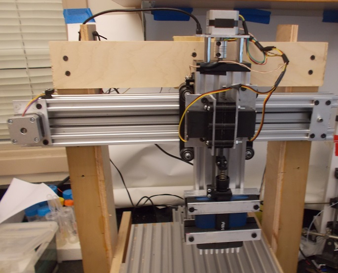
Introduction: Much biochemistry lab work consists of repetitive transfers of small volumes of solutions. Automating these tedious tasks frees lab personnel to perform other tasks and can prevent repetitive stress injuries in workers that require thought. Until recently, prices for laboratory robotics have seemed outrageously high, given that these instruments perform essentially the same tasks as those performed by low cost 3D printers. In this report, we document our initial efforts to develop an open-source DIY pipetting robot. Our robot incorporates an eight-channel mechanical pipette, the mechanical hardware to positioned it in three dimensions relative to the work surface, electronic hardware, microntroller firmware, and a graphic user interface. In this research note, we describe the mechanical and electronics aspects of the project. We will discuss the firmware and user interface in the future. While multi-channel pipettes are expensive, if you happen to have a spare one laying around, this robot (shown in Figure 1) can be built for ~$500 in materials. While this robot lacks some of the functionalities of the more expensive commercial options, the hardware and software we describe can be easily expanded upon by anyone with the desire to do so.
The robot frame assembly:A plywood frame was built and the extruded aluminum rails were mounted to it. The rails (C-Beam rails from OpenBuildsPartsStore.com, item 50-LP, 1.5 m for $40) allow three-dimensional positioning of the pipette. The pipette is mounted to the z rail (as described in the section below), which rides on a wheeled gantry plate mounted on the x rail. The work surface is mounted to another gantry plate that rides on the y rail. Stepper motors to move the work surface and pipette were attached to the x, y and z rails. While we used NEMA 17 sized motors for all three axes, in the future, we will use a more powerful NEMA 23 motor on the z axis. The z rail is moved by a 8 mm lead screw, attached to the z stepper motor using a flexible coupling. The plastic drive nut for moving in the z direction was attached to the plate joining the x and z axes. Timing belts are used to control motion in the x and y directions. Belt drives utilize standard GT2 (2mm pitch, 5mm width) timing gears, idler pullies and timing belts. The belts are attached to the gantry plates using angle aluminum brackets. Limit switches were attached to the x, y, and z rails via 3D printed plastic mounts.
A 11" by 14" work area base was assembled using four pieces of extruded aluminum rail to allow attachment of target items (such as the pipette tip box, 96 well microtiter plates, etc.). This arrangement allows us to secure the targets using bolts and drop-in nuts. The work area base was bolted to the wheeled gantry plate on the y axis. Plastic pieces to secure target items to the platform were fabricated out of PLA using a 3-D printer.
All plastic parts were designed using the program Sketch-up and exported as STL files. The program Cura was used to generate g-code, which was printed using a standard 3-D printer.
Mounting the pipette: The top portion of the pipette that
allows manual manipulation was removed. Plastic mountings for the pipette were
designed and 3-D printed. The plastic
supports were, in turn supported by aluminum angle mounts. Care was used to
ensure the mounts did not interfere with the eject mechanism. The pipette and
its mounts were bolted to the z rail.
Pipette control: The mechanical pipette is controlled by two servo motors bolted to the z rail. One of these was a standard analog servo, used to eject the pipette tips. The other was a digital servo (model d165MW) which was selected for its greater power and improved control. The digital servo was used to control injection volume. Each motor acts via rack and pinion mechanism. Steel gear racks (32 pitch 14.5 degree pressure angle, item 6295K11) were purchased from McMaster Carr. Spline mount gears (32 pitch) were purchased from Servo City and were attached to the servo motors. The tip ejection motor used a 16 tooth gear, the injection control motor used a 20 tooth gear (with 25T spline, ServoCity PN:615302) to allow the complete range of the pipette's motion. The servos were bolted to mounts that were fabricated from a combination of aluminum angle bracket and 3-D printed plastic spacers. A screen shot showing the design of one of the plastic spacers and photos of partially assembled motor mounts are shown in Figure 2. This combination allowed us to precisely position the motor and gear rack so that the teeth meshed appropriately. The servo motor mounts were bolted as a unit to the z rail. The ends of the gear racks were fitted with plastic pieces were designed and fabricated to interface with the corresponding parts of the pipette.

Electronic hardware: A Tiva C Launchpad Evaluation Board was attached to the back of the wooden frame.

A lab designed shield with
connections for three Pololu type stepper drivers, up to five servo drivers,
limit switches, and a power jack was fabricated by OSHPark. The shield also has a voltage converter that
generates the +6 volt source necessary to run the servos. Three copies of this shield can be ordered
from OSHPark for ~$25, from here. The shield was
assembled and connected to the Tiva C Launch Pad Evaluation Board. A standard 12 volt 1 amp DC "wall wart" was
used to power the robot. Wires attaching
the three stepper motors were soldered directly onto the panel. The three limit
switches were each wired to the shield.
One wire from each limit switch was held at +3.3 volts while the other
went to a GPIO pin set up to read with an internal pulldown resistor. The servo
motors were wired to the shield with +6 volts, ground and control connections.
Future directions: We are in the process of writing software to control the robot. We have made good progress on the microcontroller firmware (written in Energia) and on the user interface (written in Processing). The software will be documented in future research notes.
1 Comments
Very interesting. I don't know if a chemist or biochemist who doesn't get tired of pipeting. And the robotic ones are expensive. Looking forward to the rest of the articles!
Reply to this comment...
Log in to comment
Login to comment.