What I want to do
Use the coqui as a way to teach kids about how they can find their own scientific methods to investigate the world around them
Plug into a wider concept of leadership and how to take action on local environmental concerns.
- Replicate the Coqui Activity
My attempt and results
This was a collaborative effort with two other environmental educators. We attempted to replicate the coqui activity, modified to work in a 2 hour timespan. The activity is great, and clear! If I were doing it again, I would have also read Don Blair's original activity for more information: https://publiclab.org/notes/donblair/09-30-2014/coqui-bbv1-0
Logistics
- First, we created a list of instructions from the activity, and provided a copy of those to each group. We also drew a big picture of the circuit diagram.
- Our breadboards didn't have nice Vcc or Ground sections like those pictured in the activity, so we decided to use one row of pins at the top of the board as Vcc and a row at the bottom as the ground.
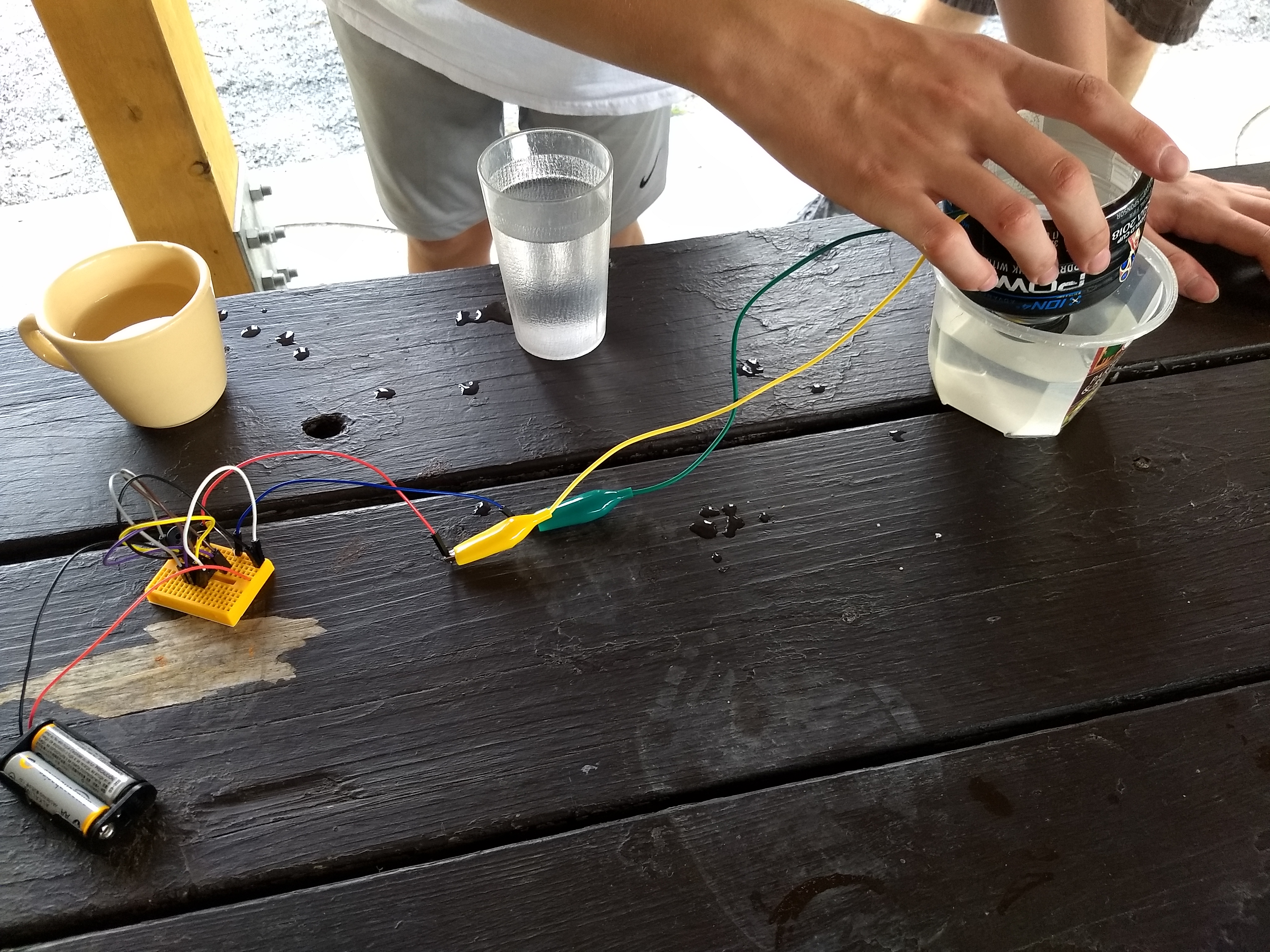
- Instead of screws, we used paperclips through the bottle caps. They were super effective! Sports drinks (like gatorade and powerade) were used preferentially due to their larger caps and larger bottles.
- We had just enough time to introduce, build, and troubleshoot the coqui with the photodiode, and then switch it out for the DIY conductivity cell in our 2 hours.
- The battery cases were tricky to get batteries back out of. I used a pen.
Environmental Education Outline
For my lesson (teaching 8 teenagers and one volunteer) I decided to focus on bigger picture issues of leadership and science rather than dive into the nitty-gritty of the technology.
We started with a brainstorm of what the words "Environmental Leadership" meant, both together and separately. The participants then wrote and shared "Why" environmental leadership was important to them, and "How" they could accomplish it (using a lot of the examples they came up in their brainstorm). Then we moved onto the "What" of the lesson -- measuring water pollution with the coqui.
We talked about how de-ionized water doesn't conduct electricity, because there's no path through the water that electrons can take. However, when there's "stuff" in the water that can conduct electricity, there is a path. Particularly if the "stuff" is something like salt. (I drew the chemical structure of Na+Cl- so the participants could see how it could dissolve in water, and handwave how electrons could flow between them.
I shared how I was curious about road salt in my community, and searched on the internet to find if there was a way to measure it, and found public lab (which is a simplified version of the true story). The coqui is an example of DIY science that can let us find answers to our own questions about environmental problems.
Building the Coqui
We then built the coqui, in pairs. I warned participants to wait until the end to put the batteries into the enclosure (having slightly shocked myself when testing it out) Participants were challenged by this instruction, as putting the batteries in is the most recognizable part of the coqui. Participants were also challenged by the "row 1" and "row 2" portions of the instructions, but these were good challenges that they were able to overcome using the circuit diagram and each other as resources.
Here's how we did it.
Procedure
- Participants had cardboard cutouts to serve as their "desk" to keep all components on, while working on this outside. These cardboard slates were also used as backs for writing on paper earlier.
- Each individual component (breadboard, capacitor, photodiode, etc.) was passed out to each group one at a time, so they knew what they were, and so I knew that each group had received a complete set. I would ask for the complete set back at the end. I heard from my coworkers that a previous group had walked away with some of the parts (one capacitor and one photodiode) and I wanted to prevent this
- I explained how the breadboard worked (pins in each row are connected to each other, the columns are independent, we're re-creating the circuit diagram)
- I asked them "Do you think this will work the first time?" (A: No) so expect to take time going back through the instructions afterwards to troubleshoot it
- The step-by-step instructions were passed out, and the participants got started
- Once a group got it working, they walked around letting different amounts of ambient light trip the sensor
- An interesting side experiment was using the coqui as a hearing test -- the teens could hear much higher frequencies than I could
- Once they were tired of experimenting with the diode, I asked the successful groups to help me troubleshoot with the groups still in progress. (We were eventually able to get all-but-one group to successfully build their coqui. I still have to troubleshoot that last kit...)
- I asked one group to switch out their photodiode with the conductivity cell and try measuring 3 previously-collected water samples with it, and try to figure out what they were. I didn't tell them, but one was tap water, one was salt dissolved in tap water, and one was lake water
- In the remaining 15 minutes, I asked them to gather around and make their final guesses as to which water sample was which. I then revealed the answer and asked if it made sense. (They could tell lake water from the color, but they thought the high-pitched one was tap water, and the other low-pitched one was polluted water of some kind). I asked them what else they could think of to measure, and how they would be able to use this
- As a reflection, the participants wrote one specific thing they had fun doing, and one thing they learned.
Questions and next steps
Changes
- Keep the 555 timer attached to the breadboard when not in use. This keeps it in good condition
Next Steps
- Troubleshoot the kit that didn't work
- Post pictures of the instructions we made
- Order some replacement parts from digikey, mouser, etc.,
Why I'm interested
- I wanted to see if the coqui could make sense in a context of noticing things in your local environment you're curious about, and finding resources online (for example, at public lab) that help you measure these things, and then feel empowered to take some kind of action with that information
- I hope these kids will remember this experience and build upon it later in their lives.
Photos (they were all so huge!):


25 Comments
Love this! Super 😃
I worried about this but the smaller ones are so cute! @zengirl2 worked on some materials for the smaller boards when we were at #makerfaire ... the larger boards are not much more expensive. I'm torn. I'm glad you didn't seem to think it was a terrible problem.
I would LOVE to see your written instructions! We're thinking of doing an activity like this with Clara S. from Brown and this is really great to see. Thanks for sharing!!
Reply to this comment...
Log in to comment
This is a great write-up on this activity. As @warren mentioned I did this activity at MakerFaire with a very broad age range 6-60. Because I was brand new to Coqui, and the new tiny breadboards were different than those used in the original write-up, @warren helped me to figure out new wiring that would work. Since our booklets no longer matched the new wiring, I made a Fritzing diagram to make things easier to understand. These diagrams became like little placemats at the table (we taped them down so they wouldn't walk :D). Anyway, with parts in cups in the middle of the table, it became very easy to get this activity to work in about an hour. I only did handholding for first placing the timer to make sure that it was positioned properly, and from then on all the kids were able to do the wiring themselves. These boards are tiny and the positions are very difficult to read for older people or children with vision issues. Anyway, I'm happy to say that out of about 60 people or so that did this activity, only 2 had issues, but I'm sure they figured it out once they got home. We did a quick test simply using two wires taped together as a probe in two solutions of water--one from a drinking fountain and one from a bottle of spring water. It was great to hear the two different tones and kids were excited to take it back home to test their own water.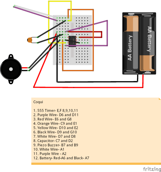
Reply to this comment...
Log in to comment
Hi @zengirl2 , you are awesome for re-working the wiring diagram! i just followed your updated instructions in preparation for doing this activity with young people in a couple weeks. Works great. Would love if you could post this diagram in its own note so we can promote it as the primary assembly activity for the store's version of the Coqui. Let me know if i can help make a draft or something.
My next goal is to slow the high-pitched buzzer down to be lower in tone and slow enough to be able to hear the separate clicks that are slower or faster depending on the conductivity of the solution. I am trying the different capacitors -- the black one that looks like a small barrel, and one that looks like the tan-blob-on-stilts. Can you recommend / draw how to either use the various capacitors or somehow add the resistor? The parts that i have available are depicted here: https://store.publiclab.org/collections/education/products/coqui-bbv1-0-conductivity-sensor
Thank you!
Is this a question? Click here to post it to the Questions page.
Reply to this comment...
Log in to comment
I'm having trouble getting our demo Coqui to work -- these breadboards don't really last... but just to break out this one point, @liz - you mentioned on a phone call that you're looking for more volume but here you are asking for lower frequency -- did you want both?
Would you mind posting this at https://publiclab.org/coqui? I think I have an answer for at least one of these Qs, and will try getting this old Coqui to work to test it out.
Is this a question? Click here to post it to the Questions page.
Reply to this comment...
Log in to comment
Hi, all, i finally got it working... you know, I think i'd had a couple things wrong, but also the long wires (although easier to insert) make it really hard to see where the wires are going, and come out more easily.
What do you think about this type of wire, which while it's harder to assemble, is much easier to debug and more similar to the Fritzing diagrams?
Is this a question? Click here to post it to the Questions page.
Reply to this comment...
Log in to comment
@warren - that looks great. Waiting on some 555 timers so I can try this out too.
Reply to this comment...
Log in to comment
OK, also just a note, i had trouble w the placement of the orange wire, which in Leslie's diagram goes to a spot one pin higher than in my version. Mine is a red wire and basically my circuit swapped the two circled wire endings in order to work.
I think it's almost identical because the top two rows could almost be swapped to counteract my change, but i need to test it to be sure.
Reply to this comment...
Log in to comment
@warren I like these short wires because they tend to stay in place better when inserted, and they also aren't like sloppy spaghetti. :) If you like this configuration we can always update the Fritzing diagram. So, @liz once we agree on the diagram where do you want a new note placed on the site?
Is this a question? Click here to post it to the Questions page.
Reply to this comment...
Log in to comment
I think an activity on /coqui would work.
I was also able to confirm that adding a resistor in-line with one of the probe wires lowered the frequency! Much lower and less annoying. Updating on the question too.
Reply to this comment...
Log in to comment
I have never seen wires like that, and they look awesome! I would love to give my kids the choice of which style of wires to use!
Also, these are the written instructions we used (courtesy of my friend and coworker, who also made the bottle cap probes).
If I were doing it again, I'd place the 555 chip for them, and leave it there to avoid damage, and adjust the instructions accordingly.
Reply to this comment...
Log in to comment
@liz it would be super cool to have a module where the participants could build it this way, and then add components or otherwise change the circuit to achieve those slower clicks!
One thing i unexpectedly really liked about the current high pitched nonsense is that, when first built with the photodiode, and brought gradually from the shade into the sunlight, we heard it rise and rise in pitch - until it seemed to drop down again an octave or two, and start rising again. Is was really cool and we all wondered why it did that.
Reply to this comment...
Log in to comment
Translating instructions to spanish in 3, 2, 1...
Reply to this comment...
Log in to comment
@xose awards a barnstar to pdhixenbaugh for their awesome contribution!
Reply to this comment...
Log in to comment
SPANISH INSTRUCTIONS
-1) Antes de empezar familiarizate con los elementos. Recuerda realizar un paso de cada vez y ayudar a otros grupos antes de seguir adelante si acabas antes que ellas.
0) Coloca con cuidado el chip temporizador 555 en el centro de la breadboard. Es difícil de reubicar. Si necesitas ayuda, pregunta por favor.
1) Conecta el pin 4 del chip 555 a la corriente (+Vcc)
2) Conecta el pin 8 del chip 555 a la corriente (+Vcc)
3) Conecta el pin 1 del chip 555 a tierra (GND)
4) Conecta el pin 3 del chip 555 a una columna separada en la breadboard. Llamaremos a esta columna ''columna #1'' y haremos en ella otras dos conexiones.
5) Conecta el pin 2 del chip 555 a una columna separada en la breadboard. Llamaremos a esta columna ''columna #2''.
6) Conecta el pin 6 del chip 555 a la columna #2.
7) Conecta la columna #1 y la columna #2 con la fotoresistencia.
8) Conecta la columna #1 a tierra (GND) con em altavoz piezoelectrico. Puedes conectarlo en cualquier orientación.
9) Conecta la columna #2 a tierra (GND) con la resistencia.
10) Conecta la batería. El cable rojo va a la corriente (+Vcc) y el cable negro a tierra (GND)
Reply to this comment...
Log in to comment
Amazing!
I've been trying to further simplify the wires-as-diagram version to make adding a resistor easier and also just have fewer weird routings and avoid the tiny wire that's hard to insert w fingertips... How's this version? Watch the white wire, sorry I ran out of colors...
Is this a question? Click here to post it to the Questions page.
Reply to this comment...
Log in to comment
I could also have those wires go over the chip, would that be confusing?
Is this a question? Click here to post it to the Questions page.
Reply to this comment...
Log in to comment
Like this... Sorry, now running out of light!
Reply to this comment...
Log in to comment
I personally think it's cute to have the wires do a criss-cross over the 555-timer, and it kind of keeps them out of the way....does it mess up the function at all?
Is this a question? Click here to post it to the Questions page.
Reply to this comment...
Log in to comment
Nope, just thought it might be confusing in a diagram, but it saves space.
On Tue, Nov 27, 2018, 4:51 PM \<notifications@publiclab.org wrote:
Is this a question? Click here to post it to the Questions page.
Reply to this comment...
Log in to comment
I think that crossing the wires over the top makes it harder to see which pins are connected. It does save space, but as a teaching aid I think it would be confusing.
Reply to this comment...
Log in to comment
@warren I'm with @Liz that it looks cute. Also, on a Fritzing diagram I think this will be clear enough. It is actually easier to find the hole for a wire when you can count its proximity from a nearby wire that is in a hole--especially since the letters and numbers on these small boards are so hard to read. That's how most of my kids were navigating--by a previous placed part or wire. If you think this is a good final version I can do the update on Fritzing and post.
Reply to this comment...
Log in to comment
I tried doing a layout as @akshaya has done on a bigger board (https://publiclab.org/notes/ashkaya/09-17-2016/build-a-coqui-a-simple-water-conductivity-sensor), but it wasn't very straightforward; uploading in a sec...
Reply to this comment...
Log in to comment
Reply to this comment...
Log in to comment
So just finally circling back here; I'm happy to post step-by-step photos and to put notes on all existing Coqui docs if we are pretty much OK with the smaller board. For me, the #1 reason is actually that so far I haven't been able to simplify the larger board... strange but the smaller board seems actually simpler. @zengirl2 if you would be willing to Fritzing the diagram, I can photo the build steps and we can post a new revision of the board with these.
What I'd like to propose is posting a "response" to this, and then adding a notice at the top of each Coqui-related page that links to this latest version, to try to get all the docs across the site synced (but without deleting old versions). How does this sound?
Thanks, everyone!
Is this a question? Click here to post it to the Questions page.
Reply to this comment...
Log in to comment
Hi all! With help from @zengirl2, @asnow and @bronwen, we've posted a new Coqui activity with a smaller breadboard and flatter wiring here: https://publiclab.org/notes/warren/03-01-2019/build-a-sound-generating-coqui-conductivity-sensor
Reply to this comment...
Log in to comment
Login to comment.