Goals:
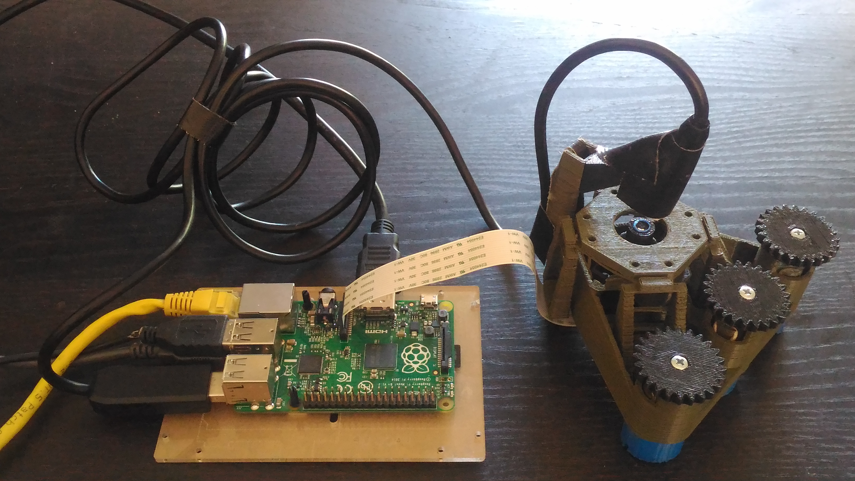
Determine if The Open Flexure microscope can replace expensive lab microscopes in the analysis of Passive PM monitors. In this note i’ll describe how I replicated an early version of this 3D printed microscope and slide stage, my experiences, assembly issues, and suggestions.
I’ll round out by discussing the next stage modifications to the OpenFlexure microscope to add a higher magnification lens and motorize the slide stage. This microscope is the second part, along with ImageJ software automation
What make the OpenFlexure microscope so cool?
The OpenFlexure microscope replaces almost all meshing geared parts in an automated slide stage with four-bar linkages that print in a single 3D print without supports. These flexing plastic joints give extremely good stability and smooth motion to the slide stage, reducing the difficulty of manufacturing dramatically. This is a brilliant mechanical re-imagining of a microscope's parts around 3D printing and flexible plastic joints, or "live hinges" as they're called in plastics manufacturing.

While the area of the slide stage is only 4x4x8mm, that is plenty of space to analyze the small samples we'll use. It will also be used by the WaterScope group for similarly sized samples for bacteria counting.
Equipment and Instructions
I started from the first draft instructions up on Docubricks. I downloaded the instructions and was able to open them in Firefox. The instructions are still in an early stage, I suggest you read them completely before assembly.
Notes on the instructions’ parts list: you don’t need hex-head m3 screws and I couldn’t find those in US hardware stores.

Tools:
- M3 screwdriver
- needlenose pliers
- 3/32” drill bit (specifies METRIC)
- Well-tuned 3D printer
Raspberry pi equipment:
- Raspberry Pi
- Raspberry Pi Camera
- Keyboard, Mouse
- HDMI TV, monitor, or converter
- microUSB power supply, 2A or above
Materials:
- 3x 30mm M3 Hex head screw
- 6x m3 washer
- 2x 8mm M3 screws (pan head)
- 6x rubber bands 1mm cross section by 15cm unstretched
- white LED, 3mm dia. (or other hacked light)
- ~40 ohm resistor (or two 22 ohm resistors in series)
- jumper wires for Raspberry pi to LED
Open Flexure microscope parts to print: The instructions suggest (kind of buried) that the dovetail joints between the microscope body and lens assembly and light holder will work better if the small parts are not printed one at a time, but instead printed all together, because it slows the layers cooling and produces more accurate parts.
test your printer with just_leg_test.stl
Print:
- 1x piscope_5_12.stl
- 4x untitled_foot.stl
- 1x camera_lens_pliers.stl
- 3x gear_elevator.stl
- 3x gear.stl
- 1x illumination.stl
- 1x optics_all_in_one.stl
- 2x sample_clip.stl
You don't need:
camera_board_gripper.stl camera_cover.stl
There is a part missing from the list, the "rear foot", which I hacked together from one of the regular feet and a couple of rubber bands (below).
Assembly issues and suggestions
I'm not going to go step-by-step through the instructions here, I'm just going to highlight some issues I had and design suggestions for the microscope and instructions.
Printing
I had a heck of a time printing, since the main microscope body takes 5-7 hours to print at low-medium resolution. That is longer, apparently, than our Makerbot or the Makerbot 2X's at Ctrl-H could stay in tune, and the prints failed either in the plastic extrusion, bed adhesion, or bed leveling which caused layer adhesion issues. In the end the only finished parts I got out of our Makerbot were the feet.
I used PSU LID's Ultimaker 2 and Mojo printer from Stratsys. It took about 14 total hours of machine time to print the parts, not counting failed prints. This is a prodigious printing project for a good, in-tune printer.


The Feet & Gears
Get the Gears together like this, and then press the screw's head down into the gear against a table:

Holding the nut in place while tightening the screw is hard. It would be much easier if this hexagonal shaft was smaller and held the nut from turning. As is I was able to pin the nut as shown and tighen it on:

While the instructions describe Pulling the rubberbands through the feat and up and over the levers as "tricky," I would say it was absolute hell. it took over an 1 hour per gear to assemble these, four hours total.
Hand position:

The quadrupled rubberbands have to go. They don't seem to fit in the slots provided, and make the microscope a bit wobbly. Quadrupled rubber bands broke repeatedly during assembly and I i used doubled bands:

Doubled rubber bands were still hard. This should be a single rubber band of the appropriate strength, here's a chart of standard sizes (US).
I used the slide clip to hold the bands in place while feeding through the microscope body:


The hook (pictured above) for rubber bands had no space to maneuver, and the bands get roughed up sliding through this narrow channel. There needs to be a channel on the side of the gear stack for the hook, that would greatly simplify this step.
There was no rear leg in the print files folder, so I printed an extra leg and strapped it to the base with a rubber band. It works alright.

The light
I didn't end up using the LED, since it turns out I only have 5mm LEDs in my stash. I modified the light assembly to hold a broken endoscope with dimmable LEDs:


in attaching the dovetail jointed light holder to the microscope's main body I broke the 'tower' it was mounted on and had to super glue it back together. it broke again while attaching my light, and I glued and stinted it together, but this part needs to be stronger or thicker, I think.

In the end this light works well. I would consider buying a new endoscope for this part, and using the webcam to show the sample and table position during educational lessons.
Capturing with Raspberry Pi
See the camera documentation
open a preview window on the command line: raspistill -p ’100,100,740,580’ -t 60000
which starts a window 100 pixels from the top of the screen, 100 pixels from the left, 480 high, 640 wide. -t 60000 sets it going for ten minutes.
I then cancel the process with ctrl-c
and take a still:
raspistill -n -o 16042016_sample_1.tiff
-o is for capturing a file, -n prevents a preview window from opening
Future parts:
The next step is to add a better lens, or "objective." @TonyC and Richard Bowman and I have talked back and forth, and we believe this is the objective that fits, sold on Alibaba.
The Objective is:
- 40x
- RMS mount
- 160mm focus
- NA 0.6-0.8
Richard Bowman's notes: The ones I used had a conjugate distance of 160mm, but it's possible the difference between 195mm and 160mm is simply that they've measured from the front rather than the back of the lens...
the objectives we bought were also advertised as 195, but they are standard 160mm tube length lenses - this is what's marked on the barrel. 195mm is the distance from the sample to the image, rather than the distance from the objective's shoulder (above the thread) to the image plane - which is what the RMS standard says should be 160mm as I understand it.
Motors and Automation: Coming soon!
11 Comments
Hi Matt, good to hear you got it working :) I have switched to single elastic bands now, and you're right, it does make it much easier. The instructions used the bands I had at the time, but the next revision will have single bands. I am also trying to work out a way of pulling them through from the bottom, which would make it much easier to do without fouling the gears. The illumination tower is a big weak point, and the next version makes it a separate clip-on part. Hopefully that will solve quite a few problems, but I'm still tweaking that design. Hopefully in a few weeks v5.15 will be ready for others to play with (you can see my progress at the moment on github). A 5mm LED mount would be really easy to add, so I'll put that on the to-do list.
Richard
Reply to this comment...
Log in to comment
Awesome Richard, thanks! The basic mechanism of the rubber bands works flawlessly, the smooth motion is really impressive. I have to post a video of a smooth "flyover" of a microscopic part to show how smooth the whole thing is!
Reply to this comment...
Log in to comment
Super. Oh, and I meant to say - the hexagonal holes are deliberately oversized, they taper down at the end to grip the nut firmly. The idea is you should be able to push-fit the nut (at least well enough that it stays in until you screw into it from the other side) then fully tighten it by screwing the thumbwheel tight. If I can sort out putting the elastic bands in from the bottom, this will all flow much better in the assembly.
Reply to this comment...
Log in to comment
I was able to get one of the nuts to sit firmly at the bottom, but the other two wouldn't. My print might be a little messy there, I'm not sure. One thing that was helpful was screwing the nut a 1/2 turn onto one bolt to hold it in place and tightening the other bolt from the other side. The tricky thing about that was how thin the nuts were.
If there were thicker nut sizes (metric hardware is a little under-stocked in the US) this technique would be easier.
Reply to this comment...
Log in to comment
Hmm, yeah - getting things to reliably push-fit without crazy excessive force is quite tricky between printers, it could just be that your printer oozes a bit more (or a bit less) than mine. I could make the tapered part a bit longer, that might help...
Reply to this comment...
Log in to comment
I'd like to do a screencap to show just how smooth this movement is. This is so cool to see in action. Exciting to see it built from plans to deployed tool! Very cool!
Reply to this comment...
Log in to comment
@mathew any progress on this build? I was interested in giving it a shot myself but wasn't sure where to start since I've seen very little activity.
Regards, SD:
Is this a question? Click here to post it to the Questions page.
Reply to this comment...
Log in to comment
Hi, @squattingdog - we've been working on an "introductory" microscope build that's an easier stepping stone to this one, which you can upgrade later. Check it out!
http://publiclab.org/basic-microscope
Reply to this comment...
Log in to comment
Hi @squattingdog, just thought I'd pop up and say that the openflexure microscope is still very much under active development - I've improved my build instructions and (finally) got them online at the github repository: https://github.com/rwb27/openflexure_microscope/
The basic microscope linked above is probably a simpler starting point - the openflexure microscope is aimed at the high-magnification end of things, where good motion control becomes super important and automating the motion of the stage really matters.
Reply to this comment...
Log in to comment
Indeed -- we're hoping the basic microscope kit will create an influx of folks who go on to make openFlexure microscopes!
Reply to this comment...
Log in to comment
Thanks @warren and @richardbowman for replying, it's appreciated. I'm quite familiar with microscopes and macro photography. I have a Nikon Optiphot Biological microscope and a Nikon MM-11 (DIC, POL, BF, epi-fluorescence, epi DIC etc.) setups. I just thought this would be a interesting project. I wasn't even sure which build I wanted to give a try.
Reply to this comment...
Log in to comment
Login to comment.