Last month I wrote a research note (http://publiclab.org/notes/nedhorning/06-30-2015/automating-ndvi-calibration) about progress made toward automating the calibration of digital photos for the purpose of creating NDVI images. This note reports on the next step which was to write an ImageJ/Fiji plugin to make this method more accessible.
The plugin works quite well on both RAW and JPEG images. For RAW images I first convert to TIFF using the following dcraw command: “dcraw -r 1 1 1 1 -o 0 -q 0 -4 -T CRW_1530.DNG” where “ CRW_1530.DNG” is the name of the RAWS file created using CHDK. This seems to do a pretty good job preserving the raw pixel values.
There are two plugins. The first calculates calibration parameters and the second applies those parameters to a directory of images. One caveat for now is that the images to be corrected must have the same camera settings (shutter speed, ISO...) as the image which was used to calculate the calibration parameters.
The plugins have two options. The fist allows you to subtract a percentage of the NIR pixel values from the visible pixel values. This is useful since the visible channel records both visible and NIR light. There is also an option to apply a correction to remove the effect of the gamma correction that is applied by the camera when using JPEG images. The default value of 2.2 should work since it seems as if most digital images created by point-and-shoot cameras use the sRGB color space. The gamma correction at this point is quite simple (correctedValue = pow(pixelValue, gammaValue) but I may use a more accurate correction in the future. It is not necessary to use the gamma correction when using raw images.
The first plugin assumes there is a calibration target in the image that can be used to calculate calibration coefficients and that the reflectance properties of target are known. It is recommended that at the very least a bright (although not so bright that image bands are saturated) and dark reference calibration target be in the image but additional targets can be used. I have been using tar paper for the dark target and printer paper for the bright target since I have spectral reflectance data for those materials (see http://publiclab.org/notes/nedhorning/05-01-2014/improved-diy-nir-camera-calibration for more information).
Before running the plugin you must create a comma-separated variable (CSV) file with the reflectance values for each of the reference targets in the image that you want to use to calculate the calibration coefficients. The rows of the CSV file correspond to the targets and the columns are the target reflectance values for the visible and near-infrared wavelengths that correspond with the camera filter being used. For example the following is what my CSV file looks like.
0.86696300, 0.90032700
0.04748605, 0.05665055
The first line is the bright target reflectance values corresponding to the visible band wavelengths (I used the reflectance at 660 nm) and the near-infrared wavelengths (reflectance at 850 nm) respectively. The second line are the visible and nir reflectance values for the dark target. There is no limit to the number of targets that can be used but at least two are required. The reflectance values in the CSV file will be used to calculate a linear regression between the target reflectance values and the pixels values in the image of the calibration targets.
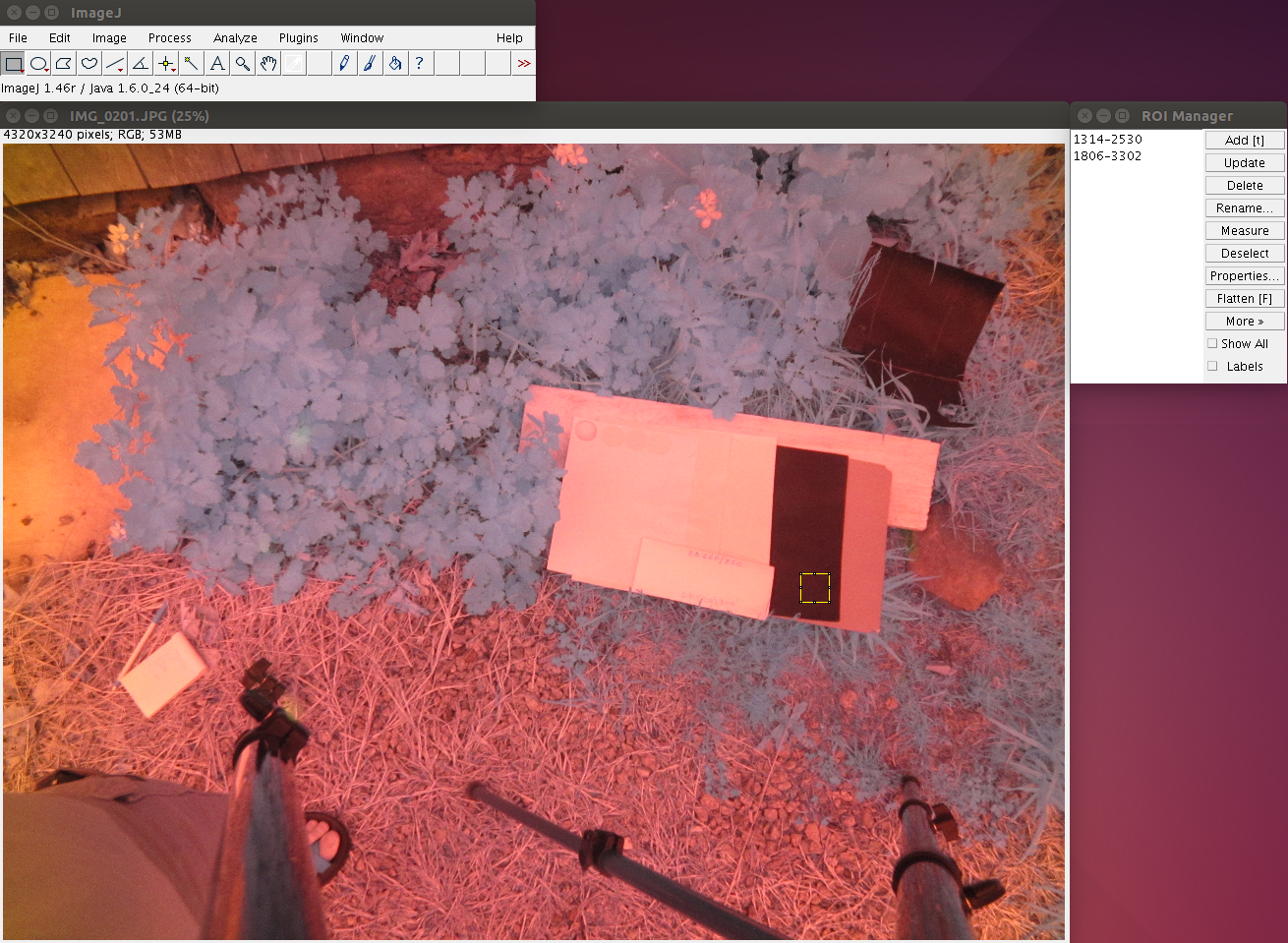
When you are ready to do the calibration you must first open the image to be calibrated in ImageJ and select a region of interest (ROI) for each of your reference targets using the ROI Manger in ImageJ (Analyze=>Tools=>ROI Manager). The ROIs will be used to select pixels from the image and the average pixel value will be used to calculate the linear regression with the target reflectance values saved in the CSV file. The order of the ROIs in the ROI Manager list (the left panel in the ROI Manager window) is important. The first (top) ROI corresponds to the first line in the CSV file, the second ROI is for the second line in the CSV file and so on. The ROI selection tools are the left-most icon on the ImageJ menu bar. I usually use the rectangle selection tool but any of the tools can be used.
Once the ROIs are selected run the first calibration plugin and the calibration parameters will be calculated. Next you can run the second plugin to apply those parameters to a directory of photos and save the floating point TIFF and or color JPEG NDVI images to your computer.
I'm looking for people willing to test this out. It is still a beta version. I need to clean up the code and I will likely make some changes as time goes on but this version seems to be working well for me. I have been very impressed with the results – even correcting JPEG images. I uploaded two test JPEG images and the target reflectance reference file to the Github “downloads=>testData directory. On my computer it takes about 10 seconds to calibrate each photo but I'm certain that time can be reduced with more clever processing methods.
This latest version of the Photo Monitoring plugin and the updated user guide can be downloaded from my Github page: https://github.com/nedhorning/PhotoMonitoringPlugin. Go the the “downloads” directory and download the file “Photo_Monitoring.jar”. Fiji can be downloaded from http://fiji.sc/Downloads. To install the plugin copy the “Photo_Monitoring.jar” file to the Fiji “plugins” directory. If you want to use the other functions that are part of the Photo Monitoring plugin you should also download and copy the other jar files from the plugin downloads page.
The next step for the plugin is to implement methods to compensate for different camera settings such as shutter speed, ISO and aperture so it is only necessary to to reduce the need to calibrate for each unique set of camera settings.
My next research note will use the calibration plugins to compare a series of different filters. If I figure out an easy way to record a video I'll post a video of the calibration process.
35 Comments
Cool.
Ned, do you have a reflectance csv file for all of the calibration targets in the test photos from iFarm (the lead image)? And a key for which target is which?
If you put two spaces at the end of a line of the csv file in the note above, Markdown will do a carriage return.
0.86696300, 0.90032700
0.04748605, 0.05665055
Is this a question? Click here to post it to the Questions page.
Reply to this comment...
Log in to comment
Chris - I'll email you the master list with all of the reflectance values for each target since they aren't really useful without the images. You need to make a different CSV file for each filter so reflectance and filter wavelengths are matched. These are the numbers for the 660/850 filter:
0.7529225,0.860895
0.753183,0.751541
0.854773 0.900327
0.0418333,0.0427029
0.3103265,0.3549215
0.04686155,0.05665055
The order is from from top to bottom of the CSV values and in the photos from left to right:
Red card stock - leftmost target White spray paint
White printer paper
Black spray paint
Gray spray paint - rightmost target Tar paper - off on its own
The tar paper is toward the upper right corner and you need to select the sample pixels from the lower part of the paper since the upper parts has some specular reflection since it's not level with the ground. It's difficult to see the edges of the red and two white sheets.
Reply to this comment...
Log in to comment
Ned, So like this.
We need to make a different file of reflectances for each filter because the filters we were using were very narrow band filters, and we want to know, e.g., how much of the red light at, e.g., exactly 660 nm was reflected off the target. I guess this will be less critical for long pass filters like Wratten 25A or Rosco #19, both of which pass most red and all NIR. For the Wratten filter, would you just use the visible reflectance at about 660nm, and NIR at about 750 nm?
Is this a question? Click here to post it to the Questions page.
Reply to this comment...
Log in to comment
Yep - that's it
Reply to this comment...
Log in to comment
Standard for an extra carriage return in Markdown is leaving a single blank line between two blocks of content - that may more sense, or be easier than the "double spaces > linebreak" trick. Discussion here
This is very cool; is it possible to have the targets arranged in a standard way as squares around a central QR code? Or even two QR codes separated by a series of squares? That would let us eventually automate the identification of the targets in the image, so if we can agree on a standard, that'd be great.
Is this a question? Click here to post it to the Questions page.
Reply to this comment...
Log in to comment
In markdown, leaving a single blank line between two blocks of content produces a single blank line between the two blocks of content. If you want a carriage return without an extra blank line, end a line with two spaces.
I guess these targets with QR codes would be used before and/or after a flight. They would be too small to place in the scene to get captured in the mapping (or other) photos.
Reply to this comment...
Log in to comment
Ah, I see - its the difference between a new paragraph and a
<br />break tag. Thanks for the clarification.Yeah, that makes sense... It'd also probably be too expensive or hard to make/distribute larger sheets with the right materials.
Ned, have you considered sun bleaching for the red card and possible yellowing for the paper? Maybe good to specify a certain brand of acid free paper.
Is this a question? Click here to post it to the Questions page.
Reply to this comment...
Log in to comment
When I first started thinking about this a couple years ago I figured auto-detecting the calibration targets would be key but that turned out to be a stumbling block since I couldn't decide the "best" way to do it. I'll probably let someone else deal with that aspect but once someone decides on a good way to do it adding the feature recognition code should be too difficult as long as a reasonable protocol was followed to help the algorithm succeed with the detection. The current manual method only take a few seconds so it's less cumbersome than I originally thought it would be.
Reply to this comment...
Log in to comment
At this point I haven't put much thought into ideal targets mostly because I don't have access to a spectrometer to measure and test different targets. I expect some commercial folks are working on it so maybe they'll come out with something that isn't too expensive. Most of the professional calibration material if very pricey.
Reply to this comment...
Log in to comment
QR code libraries are available in many languages, and most QR code libraries will probably return a location of the center of the code. But maybe not an orientation. So I figure repeating the QR code with samples along the axis at known distances (say, every 20% of the way between the two targets) is an easy standard to stick to, with some futureproofing. How does that sound? Any preferred ordering of the patches?
I'll probably do a version in JavaScript.
Is this a question? Click here to post it to the Questions page.
Reply to this comment...
Log in to comment
The panel order is not important as long as it's predictable and known. The "ideal" targets would probably be a few gray patches from bright to dark and it would be nice if the refelctance of each target was roughly similar through the visible and NIR. Some other qualities are that the samples should have diffuse (as opposed to specular) reflectance properties and as you noted the reflectance properties should be reasonably stable so they don't change over time. Weatherproof and protected would be useful for working in the field. When sampling form the calibration patches you'd make sure you sampling pixels away form the patch edges. I'm sure there are other qualities/features that other folks can add to but this is a start.
Reply to this comment...
Log in to comment
This is something that'd also benefit the general white balance process of Infragram cameras. I wonder, are there any paint sample strips that are really long-term stable, and widely available? I think we asked this early in the Infragram project too.
Is this a question? Click here to post it to the Questions page.
Reply to this comment...
Log in to comment
Have you considered using reference charts used to calibrate green rooms in cinema? Some thing like this: labsphere - Reflectance Reference Targets Tetra cam used Multi-spectral Ground Calibration Targets
Is this a question? Click here to post it to the Questions page.
Reply to this comment...
Log in to comment
Rosco manufactures outdoor-grade TV paints including 60% grey (TV white) and black (3%) and chroma colors (blue, green). They would be good choices for a DIY calibration card. https://www.rosco.com/FTVP/TVPaints.cfm https://www.rosco.com/FTVP/ultimatte.cfm
Reply to this comment...
Log in to comment
Mathew - Have you been able to find a reflectance plot for those paints? I looked but didn't see it. Other paints I was looking at a couple years ago had plots but only for the visible range. It's important to know the spectral reflectance properties into the NIR and having some assurance that it's stable over time and consistent from batch to batch would be nice too.
Is this a question? Click here to post it to the Questions page.
Reply to this comment...
Log in to comment
Please help. If it is possible to describe all the work with the plugin. How to create "сomma-separated variable (CSV) file with the reflectance values for each of the reference targets in the image that you want to use to calculate the calibration coefficients." I am using mobius cam from http://infragram.org/. Thanks!
Reply to this comment...
Log in to comment
Hi aldehyde - Did you look at the user guide on Github: https://github.com/nedhorning/PhotoMonitoringPlugin that should have information about creating the CSV file of target reflectance. Here is the excerpt from the user guide:
Before running the plugin you must create a comma-separated variable (CSV) file with the reflectance values for each of the reference targets in the image that you want to use to calculate the calibration coefficients. The rows of the CSV file correspond to the targets and the columns are the target reflectance values for the visible and near-infrared wavelengths that correspond with the camera filter being used. For example, the following values are for two targets (first line is the bright target and second line is the dark target): 0.86696300, 0.90032700 0.04748605, 0.05665055
Reply to this comment...
Log in to comment
How to get target reflectance values for the visible and near-infrared wavelengths that correspond with the camera filter? Can I use?. 0.7529225,0.860895 0.753183,0.751541 0.854773 0.900327 0.0418333,0.0427029 0.3103265,0.3549215 0.04686155,0.05665055 (Red card stock - leftmost target White spray paint White printer paper Black spray paint Gray spray paint - rightmost target Tar paper - off on its own)
Is this a question? Click here to post it to the Questions page.
Reply to this comment...
Log in to comment
Unfortunately those values would only work if you had the same materials that I used. To get the reflectance values you would either need to fine someone with a spectrometer who could scan your targets and give you the reflectance values for the wavelengths suitable for the filter you are using or purchase targets that have documented reflectance values which is usually quite expensive. Getting calibration targets that have known reflectance values seems to be the biggest hurdle for the calibration process. Most universities have spectrometers (lab and or field) so maybe if you ask around you can find someone to help.
Reply to this comment...
Log in to comment
Hi Ned,
I am really excited about the work you are doing here as it helps resolve some major issues with my grad studies. I have a few questions:
Thanks for all the effort you put into this. It's great to see opensource processing receive features that proprietary software seems to lack.
Is this a question? Click here to post it to the Questions page.
Reply to this comment...
Log in to comment
Hi Jacob, To check for aperture you could try another EXIF reader. Maybe "max aperture" is the same as "aperture" but I have no idea. When working with Pix4D if you are planning on stitching NDVI images that might be problematic since it is more difficult for Pix4D to locate unique keypoints to match in adjacent images. I would like to add a feature to the photo monitoring plugin to output calibrated image bands but am not sure when I'll have time to do that. Using calibrated image bands would probably be the best approach for creating mosaicked images (RGB and NDVI) in Pix4D and other similar software. A 20x20 pixel ROI should be fine to calculate calibration coefficients as long as the ROIs are fairly homogeneous and without edge effects where the edges values are different from the rest of the ROI.
Reply to this comment...
Log in to comment
Thanks for the feedback.
I think I misunderstood the function of this plugin. I thought I could calibrate my jpeg R/G/NIR images to a black, a grey, and a white panel of known reflectance, while attempting to return some of the linear-response of a RAW. NDVI would be done separately. My proposed workflow is:
Reply to this comment...
Log in to comment
The current version of the plugin only outputs index (NDVI and DVI) images. The plugin only calibrates two bands, a visible and a NIR band and two output a reflectance image I would with have to output two single band images or a typical 3-band image but that would require that I decide on how to deal with the third (often the green channel) band. A few people have requested this feature so I'd like to do it but not sure when I will happen. Perhaps in January.
Reply to this comment...
Log in to comment
Hello, @nedhorning, I had recently been researching about NDVI and came across your amazing calibration plugin. It works great; however I have a few question for you, if you don't mind answering them.
I am doing a research on corals in a fish tank right now and I came across with these problems
As you can see, the light that is reflecting has the highest "NDVI" value and also the reflection from the mirror also shares exact NDVI value as the object.
Thank you very much and I am sorry if I asked some stupid question because I know very little about photo shooting.
And the reason why i flipped the min max value is because it just looks more obvious that way, so I am not sure what effect it causes to the image.
I used Rosco Roscolux #2007 Storaro Blue Gel Filter
Top_Color.tif
Is this a question? Click here to post it to the Questions page.
Reply to this comment...
Log in to comment
Hi David - This is an interesting project. The reflection of the glass should affect the results as long as the reflection is not in the area of your calibration targets. If there is glass between the camera and the scene you are photographing that could have some impact on the results since the quality of the light might change as it passes through the glass. Water will have an effect on any near-infrared (NIR) imaging since most NIR light is absorbed by the water.
Another possible problem is that you use the reflectance values for the calibration target I used and they might not be accurate for the targets you are using. It's possible that the values are similar but I don't know for sure.
You didn't mention what type of filter you are using. From your settings screenshot it appears as if it is a blue filter. Is that what you are using? Another (perhaps the main) issue is that the settings screenshot is from the plugin that does not calculate or process the calibration information. For the calibration you need to use the "Calculate image calibration coefficients" plugin. Let me know if that helps.
Is this a question? Click here to post it to the Questions page.
Reply to this comment...
Log in to comment
David,
When using a blue (#2007) filter, the red channel records NIR and the blue channel records visible blue light which is used to compute NDVI. Water absorbs NIR two orders of magnitude more strongly than it absorbs blue light. It will be very difficult to capture a photograph which has good information about both blue and NIR because one of those channels will typically be either overexposed or underexposed.
Light absorption coefficient of pure water. The absorption coefficient (y axis) is a log scale so NIR light (e.g. 760 nm) is absorbed 10 times faster than orange light (625 nm).
Below is the color histogram of the bluish photo you included in your note. The blue channel (which records visible blue light) is completely overexposed (pegged at ~255). All the pixels in the photo essentially have the same value for blue, and that value is used to compute all the NDVI values.
Histogram of the bluish photo in the note. The blue channel is severely overexposed.
It should be possible to take a photo with less overexposure in the blue channel and not too much under-exposure in the red (NIR) channel. It will help to shoot through as little water as possible. It might not be possible to get NDVI results similar to those from plants in air, but your results could still have meaning when compared with themselves.
Chris
Reply to this comment...
Log in to comment
Thank you very much for the advice Chris and Ned, I have learned a lot. I will continue to this research, so if possible if I encounter any problem, can I leave my question here?
Fyi: I have tried calibrating the image; however it shows an error of Error: java.lang.NumberFormatException: For input string: ".3.5"
Is this a question? Click here to post it to the Questions page.
Reply to this comment...
Log in to comment
Hello, @nedhorning, for the Rosco Roscolux #2007 Storaro Blue Gel Filter, with the following datasheet
Could I just use the visible reflectance at about 440nm, and NIR at about 740 nm?
Are a cardboard, a white paper and a black Ethylene-vinyl acetate (EVA) good targets?
Is this a question? Click here to post it to the Questions page.
Reply to this comment...
Log in to comment
Hi - Using 440nm seem reasonable but I'd probably increase the NIR value to 760nm or beyond or something like that since the peak is probably beyond 740nm. That's just a guess since the graph is cut off. As far as advice for selecting calibration targets you could test the material you suggest - assuming you have access to a spectrometer. The best targets will have relatively flat reflectance curves (reflectance for all wavelengths are similar) but that can be difficult. In your case it would be best if the reflectance curve was flat in the NIR wavelengths since we don't know where the peak is. It's also good if the calibration target is not very sensitive to specular reflection. It's better if the light is reflected diffusely - equally in all direction.
Reply to this comment...
Log in to comment
Dear Ned Horning,
I calculated image calibration coefficients, using the reflectance data from department's spectrometer and 3 calibration targets. I found a good correlation of R2 0.9432 for Visible which at 600 nm and R2 0.84332 at reference 850 nm for NIR. But looking at the graph , i was wondering what the image values with the range (0.0-1.0) ? How i can calculate the image values manually using ImageJ and shouldn't this value be something between (0-255) as i saw in some other posts at public labs?
I look forward to hear from you Ned.
Thank you so much
Is this a question? Click here to post it to the Questions page.
Reply to this comment...
Log in to comment
Hi Suman - The values from 0 - 1 have been scaled from the original image. The reason I do this is that some image pixel values range from 0 - 255 but others can be between 0 - 1024 or 0 - 2048 for example. If you wanted to scale an image from 0 - 255 to 0 - 1 you could use this formula: Pixel_value * 1/255 Another point is that if you only have two targets then the R2 will always be 1 or very close to 1 even if the actual fit between pixel values and ground reluctance is not very strong.
Reply to this comment...
Log in to comment
Ohh I get it now. Actually the data has 3 calibration target, but i plan to increase it to 5 targets. I also wanted to know, how i can manually measure the pixel value through a rectangle selection in ImageJ. I tried using Analyze --> Measure, but all the calibration target that i measured through individual rectangle selection has similar range of mean values (250-255 range)
Reply to this comment...
Log in to comment
Thank you so much for your prompt response Ned...
Reply to this comment...
Log in to comment
Hi Suman - Using Analyze => Measure should work. It's not uncommon to have high pixel values for bright targets. In fact if the exposure isn't set well the brighter targets are easily saturated at 255. If you have calibration target images with a lot of pixels at 255 they have almost certainly saturated the sensor and it would be best to retake those photos with a lower exposure value to create a darker image using a faster shutter speed, smaller aperture or lower ISO speed.
Reply to this comment...
Log in to comment
Hello Ned, I tried using different exposure settings now, and its working, the pixels aren't saturated anymore.
Thank you so much for your prompt response as always. Highly appreciable
Best Regards,
Suman
Reply to this comment...
Log in to comment
Login to comment.